
Page 275 - Electrical Safety of Low Voltage Systems
P. 275
258 Chapter Fifteen
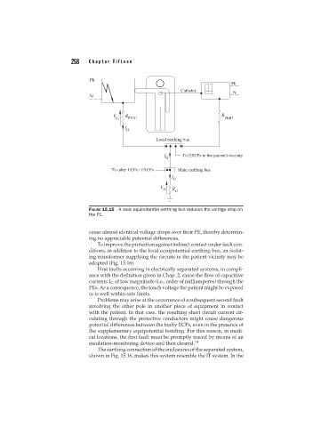
FIGURE 15.15 A local equipotential earthing bus reduces the voltage drop on
the PE.
cause almost identical voltage drops over their PE, thereby determin-
ing no appreciable potential differences.
To improve the protection against indirect contact under fault con-
ditions, in addition to the local equipotential earthing bus, an isolat-
ing transformer supplying the circuits in the patient vicinity may be
adopted (Fig. 15.16).
First faults occurring in electrically separated systems, in compli-
ance with the definition given in Chap. 2, cause the flow of capacitive
currents I G of low magnitude (i.e., order of milliamperes) through the
PEs. As a consequence, the touch voltage the patient might be exposed
to is well within safe limits.
Problems may arise at the occurrence of a subsequent second fault
involving the other pole in another piece of equipment in contact
with the patient. In that case, the resulting short circuit current cir-
culating through the protective conductors might cause dangerous
potential differences between the faulty ECPs, even in the presence of
the supplementary equipotential bonding. For this reason, in medi-
cal locations, the first fault must be promptly traced by means of an
insulation-monitoring device and then cleared. 14
The earthing connection of the enclosures of the separated system,
shown in Fig. 15.16, makes this system resemble the IT system. In the