
Page 277 - Electrical Safety of Low Voltage Systems
P. 277
260 Chapter Fifteen
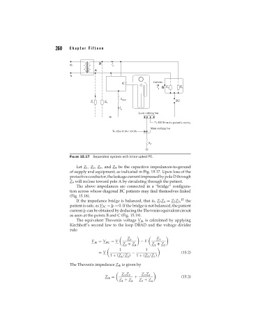
FIGURE 15.17 Separated system with interrupted PE.
Let Z 1 , Z 2 , Z 3 , and Z 4 be the capacitive impedances-to-ground
of supply and equipment, as indicated in Fig. 15.17. Upon loss of the
protectiveconductor,theleakagecurrentimpressedbypoleDthrough
Z 4 will reclose toward pole A by circulating through the patient.
The above impedances are connected in a “bridge” configura-
tion across whose diagonal BC patients may find themselves linked
(Fig. 15.18).
If the impedance bridge is balanced, that is, Z 1 Z 4 = Z 2 Z 3 , 15 the
patient is safe, as V BC = I P = 0. If the bridge is not balanced, the patient
current I P can be obtained by deducing the Thevenin equivalent circuit
as seen at the points B and C (Fig. 15.19).
The equivalent Thevenin voltage V th is calculated by applying
Kirchhoff’s second law to the loop DBAD and the voltage divider
rule:
Z 3 Z 1
V th = V BC = V − V
Z + Z Z + Z
3 4 1 2
1 1
= V − (15.2)
1 + (Z /Z ) 1 + (Z /Z )
3
4
1
2
The Thevenin impedance Z th is given by
Z Z 2 Z Z 4
3
1
Z = + (15.3)
th
Z + Z 2 Z + Z 4
1
3