
Page 278 - Electrical Safety of Low Voltage Systems
P. 278
Applications of Electrical Safety 261
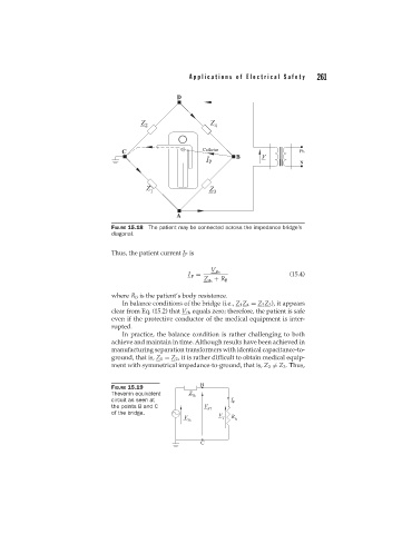
FIGURE 15.18 The patient may be connected across the impedance bridge’s
diagonal.
Thus, the patient current I P is
V th
I = (15.4)
P
Z + R B
th
where R B is the patient’s body resistance.
In balance conditions of the bridge (i.e., Z 1 Z 4 = Z 2 Z 3 ), it appears
clear from Eq. (15.2) that V th equals zero; therefore, the patient is safe
even if the protective conductor of the medical equipment is inter-
rupted.
In practice, the balance condition is rather challenging to both
achieve and maintain in time. Although results have been achieved in
manufacturing separation transformers with identical capacitance-to-
ground, that is, Z 1 = Z 2 , it is rather difficult to obtain medical equip-
ment with symmetrical impedance-to-ground, that is, Z 3 = Z 3 . Thus,
FIGURE 15.19
Thevenin equivalent
circuit as seen at
the points B and C
of the bridge.