Page 71 - Electrical Safety of Low Voltage Systems
P. 71

54   Chapter Four


                                  FIGURE 4.10 Earth
                                  resistance’s
                                  equivalent circuit.


                                  their electric potentials are not significantly affected by their recipro-
                                  cal influence (Fig. 4.11).
                                     Equation (4.9) can be generalized to the case of two dissimilar
                                  electrodes, buried at different depths and leaking different currents I 1
                                  and I 2 , by writing the following system of equations [Eq. (4.13)]:


                                                     ⎧
                                                      V GTOT = R 11 I 1 + R 12 I 2
                                                     ⎪
                                                     ⎨
                                                      V GTOT = R 12 I 1 + R 22 I 2
                                                     ⎪
                                                     ⎩
                                                       I GTOT = I 1 + I 2              (4.13)
                                     R 11 (R 22 ) is the earth resistance of the first (second) electrode, ob-
                                  tained by disconnecting the second (first) one; R 12 (R 21 ) is the ratio of
                                  the ground potential attained by the first (second) electrode, not con-
                                  nected to the grounding system, to the current flowing through the
                                  second (first) one. R 12 and R 21 are referred to as mutual resistances.


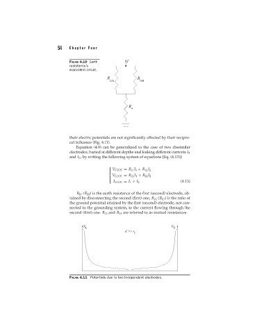
                                  FIGURE 4.11 Potentials due to two independent electrodes.
   66   67   68   69   70   71   72   73   74   75   76