
Page 66 - Electrical Safety of Low Voltage Systems
P. 66
The Earth 49
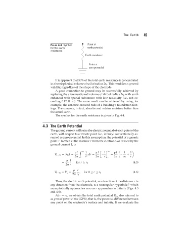
FIGURE 4.4 Symbol
for the earth
resistance.
It is apparent that 50% of the total earth resistance is concentrated
in a hemispherical volume of soil of radius 2r 0 . This result has a general
validity, regardless of the shape of the electrode.
A good connection to ground may be successfully achieved by
replacing the aforementioned volume of dirt of radius 2r 0 with earth
enhanced with special substances with low resistivity (i.e., not ex-
ceeding 0.12 · m). The same result can be achieved by using, for
example, the concrete-encased rods of a building’s foundation foot-
ings. The concrete, in fact, absorbs and retains moisture better than
the actual earth.
The symbol for the earth resistance is given in Fig. 4.4.
4.3 The Earth Potential
The ground current will raise the electric potential of each point of the
earth, with respect to a remote point (i.e., infinity) conventionally as-
sumed as zero potential. In this assumption, the potential of a generic
point P located at the distance r from the electrode, as caused by the
ground current I,is
I ∞ 1 I 1 ∞ I 1 1
V r−∞ = R G I = dr = − = − +
2 r r 2 2 r r 2 ∞ r
I
= , for r ≥ r 0 (4.5)
2 r
I
V r−∞ = V G = , for 0 ≤ r ≤ r 0 (4.6)
2 r 0
Thus, the electric earth potential, as a function of the distance x in
6
any direction from the electrode, is a rectangular hyperbola, which
asymptotically approaches zero as r approaches to infinity (Figs. 4.5
and 4.6).
At r = r 0 , we obtain the total earth potential V G , also referred to
as ground potential rise (GPR), that is, the potential difference between
any point on the electrode’s surface and infinity. If we evaluate the