
Page 64 - Electrical Safety of Low Voltage Systems
P. 64
The Earth 47
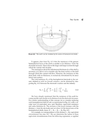
FIGURE 4.2 The earth can be modeled by the series of hemispherical shells.
It appears clear from Eq. (4.1) that the resistance of the generic
hemispherical layer of the earth is smaller as its distance r from the
electrode increases. This is due to the larger and larger section through
which the current will circulate.
The assumption about the infinitesimal thickness dx of the shell is
necessary, as it allows us to consider only the inner surface of the shell
through which the current will flow. Therefore, the resistance of this
ideal shell, with no thickness, is exclusively determined by its inner
lateral area surface.
The total resistance R G of the hemispherical electrode to the cur-
rent, defined as earth (or ground) resistance, can be obtained by inte-
grating Eq. (4.1) between the electrode’s surface and the infinity:
∞ dr 1 ∞
R G = 2 = − = (4.2)
2 r 2 r 2 r 0
r 0 r 0
We have already mentioned that the resistance of the earth be-
comes smaller and smaller as its distance from the electrode increases.
For a better understanding of this concept, let us consider replacing
each hemispherical shell of soil, as represented in Fig. 4.2, with a cir-
cular layer of equivalent area, and, therefore, equivalent resistance
and same thickness dx. The surfaces of the layers increase with the
distance r i from the electrode, just as it does for the lateral area of the
hemispherical shells, hence R i < R 2 < R 1 < R 0 (Fig. 4.3).
For example, in correspondence of the distance r i , the equivalent
2
circumference has area 2 r . We can determine the radius of these
i
equivalent circumferences from the following expression, as applied