
Page 65 - Electrical Safety of Low Voltage Systems
P. 65
48 Chapter Four
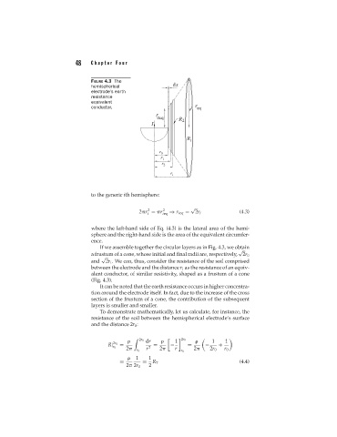
FIGURE 4.3 The
hemispherical
electrode’s earth
resistance
equivalent
conductor.
to the generic ith hemisphere:
√
2
2
2 r = r ieq ⇒ r ieq = 2r i (4.3)
i
where the left-hand side of Eq. (4.3) is the lateral area of the hemi-
sphere and the right-hand side is the area of the equivalent circumfer-
ence.
If we assemble together the circular layers as in Fig. 4.3, we obtain
√
a frustum of a cone, whose initial and final radii are, respectively, 2r 0
√
and 2r i . We can, thus, consider the resistance of the soil comprised
between the electrode and the distance r i as the resistance of an equiv-
alent conductor, of similar resistivity, shaped as a frustum of a cone
(Fig. 4.3).
It can be noted that the earth resistance occurs in higher concentra-
tion around the electrode itself. In fact, due to the increase of the cross
section of the frustum of a cone, the contribution of the subsequent
layers is smaller and smaller.
To demonstrate mathematically, let us calculate, for instance, the
resistance of the soil between the hemispherical electrode’s surface
and the distance 2r 0 :
2r 0 dr 1 2r 0 1 1
2r 0
R| = = − = − +
2 r 2 r 2 2r 0 r 0
r 0 2
r 0 r 0
1 1
= = R T (4.4)
2 2r 0 2