
Page 68 - Electrical Safety of Low Voltage Systems
P. 68
The Earth 51
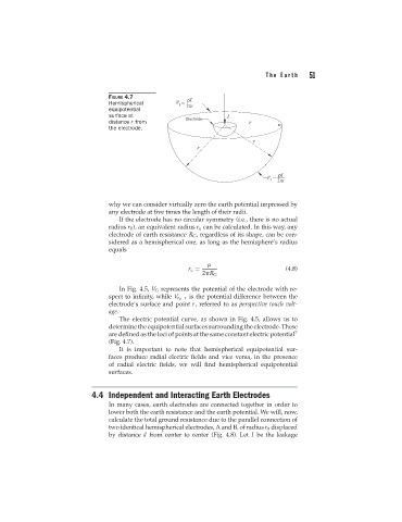
FIGURE 4.7
Hemispherical
equipotential
surface at
distance r from
the electrode.
why we can consider virtually zero the earth potential impressed by
any electrode at five times the length of their radii.
If the electrode has no circular symmetry (i.e., there is no actual
radius r 0 ), an equivalent radius r e can be calculated. In this way, any
electrode of earth resistance R G , regardless of its shape, can be con-
sidered as a hemispherical one, as long as the hemisphere’s radius
equals
r e = (4.8)
2 R G
In Fig. 4.5, V G represents the potential of the electrode with re-
spect to infinity, while V r 0 −r is the potential difference between the
electrode’s surface and point r, referred to as perspective touch volt-
age.
The electric potential curve, as shown in Fig. 4.5, allows us to
determine the equipotential surfaces surrounding the electrode. These
are defined as the loci of points at the same constant electric potential 7
(Fig. 4.7).
It is important to note that hemispherical equipotential sur-
faces produce radial electric fields and vice versa, in the presence
of radial electric fields, we will find hemispherical equipotential
surfaces.
4.4 Independent and Interacting Earth Electrodes
In many cases, earth electrodes are connected together in order to
lower both the earth resistance and the earth potential. We will, now,
calculate the total ground resistance due to the parallel connection of
two identical hemispherical electrodes, A and B, of radius r 0 displaced
by distance d from center to center (Fig. 4.8). Let I be the leakage