
Page 247 - Electrical Properties of Materials
P. 247
Frequency response 229
indices n 1 and n 2 respectively. At each interface there will be some light re-
flected and some transmitted. The reflection coefficient, from electromagnetic
theory, at an interface like (a) in Fig. 10.5 is
n 2 – n 1
r a = . (10.17)
n 2 + n 1
By symmetry, the reflection coefficient at (b) will be the reverse of this,
n 1 – n 2
r b = =–r a . (10.18)
n 1 + n 2
Now suppose that all the layers are a quarter wavelength thick—their actual
thickness will be n 1 (λ/4) and n 2 (λ/4) respectively. Then the wave reflected
back from (b) will be π radians out of phase with the wave reflected back from
(a) because of its extra path length, and another π radians because of the phase
difference in eqn (10.18). So the two reflected waves are 2π radians different;
that is, they add up in phase. A large number of these layers, often as many as
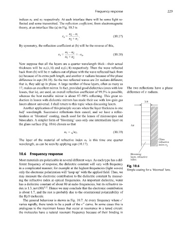
17, makes an excellent mirror. In fact, provided good dielectrics (ones with low The two reflections have a phase
losses, that is), are used, an overall reflection coefficient of 99.5% is possible, difference of π radians.
whereas the best metallic mirror is about 97–98% reflecting. This great re-
duction in losses with dielectric mirrors has made their use with low-gain gas
λ/4
lasers almost universal. I shall return to this topic when discussing lasers.
Another application of this principle occurs when the layer thickness is one
half wavelength. Successive reflections then cancel, and we have a reflec-
tionless or ‘bloomed’ coating, much used for the lenses of microscopes and
binoculars. A simpler form of ‘blooming’ uses only one intermediate layer on
the glass surface (Fig. 10.6) chosen so that
Air
√
n 1 = n 2 . (10.19)
The layer of the material of refractive index n 1 is this time one quarter Glass
refractive
wavelength, as can be seen by applying eqn (10.17). index n
2
10.6 Frequency response Blooming
layer, refractive
Most materials are polarizable in several different ways. As each type has a dif- index
ferent frequency of response, the dielectric constant will vary with frequency
Fig. 10.6
in a complicated manner; for example at the highest frequencies (light waves)
Simple coating for a ‘bloomed’ lens.
only the electronic polarization will ‘keep up’ with the applied field. Thus, we
may measure the electronic contribution to the dielectric constant by measur-
ing the refractive index at optical frequencies. An important dielectric, water
has a dielectric constant of about 80 at radio frequencies, but its refractive in-
dex is 1.3, not (80) 1/2 . Hence we may conclude that the electronic contribution
is about 1.7, and the rest is probably due to the orientational polarizability of
the H 2 O molecule.
The general behaviour is shown in Fig. 10.7. At every frequency where
varies rapidly, there tends to be a peak of the curve. In some cases this is
analogous to the maximum losses that occur at resonance in a tuned circuit:
the molecules have a natural resonant frequency because of their binding in