
Page 242 - Electrical Properties of Materials
P. 242
224 Principles of semiconductor devices
9.14. Owing to the dependence of atomic spacing on pres-
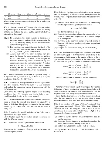
μ h μ e σ p σ n N i
–1
–1
–3
2
2
–1
–1
s )
s )
(m V –1 –1 (m V –1 –1 ( m ) ( m ) (m ) sure, the bandgap E g of silicon decreases under pressure at the
–3
Ge 0.17 0.36 10 4 100 2.4 × 10 19 rate of 2×10 eV per atmosphere from its atmospheric value
Si 0.04 0.18 10 4 100 1.5 × 10 16 of 1.1 eV.
where σ p and σ n are the conductivities of the p- and n-type
materials respectively. (i) Show that in an intrinsic semiconductor the conductivity
may be expressed with good approximation as
9.7. If a forward bias of 0.1 V is applied to the germanium
σ = σ 0 exp(–E g /2kT)
p–n junction given in Exercise 9.6, what will be the density
of holes injected into the n-side and the density of electrons and find an expression for σ 0 .
injected into the p-side? (ii) Calculate the percentage change in conductivity of in-
trinsic silicon at room temperature for a pressure change
9.8. (i) In a certain n-type semiconductor a fraction α of of 10 atmospheres.
the donor atoms is ionized. Derive an expression for (iii) Show that I 0 , the saturation current of a diode (found in
E F – E D ,where E F and E D are the Fermi level and Exercise 9.13), is to a good approximation proportional
donor level respectively. to exp(–E g /kT).
(ii) In a certain p-type semiconductor a fraction β of the (iv) Compare the pressure sensitivity of σ with that of I 0 .
acceptor atoms is ionized. Derive an expression for
E F – E A ,where E A is the acceptor level. 9.15. Take two identical samples of a semiconductor which
(iii) Assume that both of the above materials were pre- are oppositely doped so that the number of electrons in the
pared by doping the same semiconductor, and that n-type material (N) is equal to the number of holes in the p-
E D = 1.1 eV and E A = 0.1 eV, where energies are type material. Denoting the lengths of the samples by L and
measured from the top of the valence band. By vari-
the cross-sections by A, the number of electrons and holes are:
ous measurements at a certain temperature T we find
that α = 0.5 and β = 0.05. When a p–n junction number of holes LAN
p-type 2
is made, the built-in voltage measured at the same number of electrons LAN /N
i
temperature is found to be 1.05 eV. Determine T.
2
number of holes LAN /N
n-type i
9.9. Calculate the reverse breakdown voltage in an abrupt Ge number of electrons LAN.
23
–3
–3
22
p–n junction for N A =10 m , N D =10 m , r = 16, and Thus the total number of carriers in the two samples is
7
–1
breakdown field E br =2 × 10 Vm .
N i
2
9.10. Determine the density distribution of holes injected into 2LAN 1+ .
N 2
an n-type material. Assume that ∂/∂t = 0 (d.c. solution),
and neglect the conduction current in comparison with the Assume now that we join together (disregard the practical
diffusion current. difficulties of doing so) the two samples. Some holes will
[Hint: solve the continuity equation subject to the boundary cross into the n-type material and some electrons into the
conditions, N h (x = 0) = injected hole density, N h (x →∞)= p-type material until finally an equilibrium is established.
equilibrium hole density in the n-type material. Show that the total number of mobile carriers is reduced
when the two samples are joined together (that is some
9.11. Determine from the solution of Exercise 9.10 the dis-
electrons and holes must have been lost by recombination).
tance at which the injected hole density is reduced by a
factor e. Calculate this distance numerically for germanium 9.16. A pn junction LED made of GaAsP emits red light
2 –1
where D h = 0.0044 m s and the lifetime of holes is (approximate wavelength 670 nm). When forward biased it
200 μ sec. takes 0.015 mA at 1.3 V rising to 17 mA at 1.6 V. When re-
verse biased its capacity is 83.1 pF at 1 V and 41.7 pF at 10 V.
9.12. Determine the spatial variation of the hole current
Avalanche breakdown occurs at 20 V.
injected into the n-type material.
[Hint: Neglect again the conduction current in comparison (i) Deduce I 0 and the effective device temperature from the
with the diffusion current.] rectifier equation.
(ii) Assuming that the junction is very heavily doped on the
9.13. Express the constant I 0 in the rectifier equation
n-side, find the carrier density on the p-side.
I = I 0 [exp(eU 1 /kT)–1] (iii) Deduce the junction area and the built-in voltage.
in terms of the parameters of the p- and n-type materials Data for GaAsP: Permittivity = 12 0 ; breakdown field =
–1
7
constituting the junction. 8 × 10 Vm .