
Page 263 - Electrical Properties of Materials
P. 263
Piezoelectricity, pyroelectricity, and ferroelectricity 245
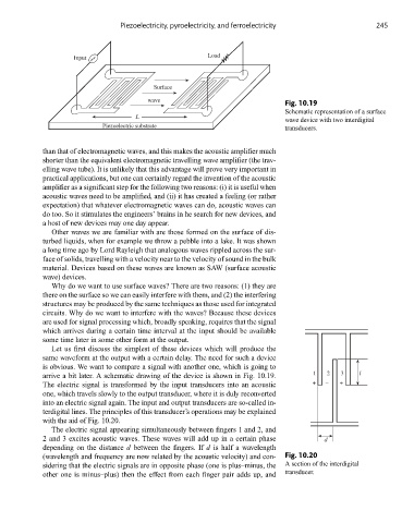
Load
Input
Surface
wave
Fig. 10.19
Schematic representation of a surface
L
wave device with two interdigital
Piezoelectric substrate transducers.
than that of electromagnetic waves, and this makes the acoustic amplifier much
shorter than the equivalent electromagnetic travelling wave amplifier (the trav-
elling wave tube). It is unlikely that this advantage will prove very important in
practical applications, but one can certainly regard the invention of the acoustic
amplifier as a significant step for the following two reasons: (i) it is useful when
acoustic waves need to be amplified, and (ii) it has created a feeling (or rather
expectation) that whatever electromagnetic waves can do, acoustic waves can
do too. So it stimulates the engineers’ brains in he search for new devices, and
a host of new devices may one day appear.
Other waves we are familiar with are those formed on the surface of dis-
turbed liquids, when for example we throw a pebble into a lake. It was shown
a long time ago by Lord Rayleigh that analogous waves rippled across the sur-
face of solids, travelling with a velocity near to the velocity of sound in the bulk
material. Devices based on these waves are known as SAW (surface acoustic
wave) devices.
Why do we want to use surface waves? There are two reasons: (1) they are
there on the surface so we can easily interfere with them, and (2) the interfering
structures may be produced by the same techniques as those used for integrated
circuits. Why do we want to interfere with the waves? Because these devices
are used for signal processing which, broadly speaking, requires that the signal
which arrives during a certain time interval at the input should be available
some time later in some other form at the output.
Let us first discuss the simplest of these devices which will produce the
same waveform at the output with a certain delay. The need for such a device
is obvious. We want to compare a signal with another one, which is going to
arrive a bit later. A schematic drawing of the device is shown in Fig. 10.19. 1 2 3 l
The electric signal is transformed by the input transducers into an acoustic + – +
one, which travels slowly to the output transducer, where it is duly reconverted
into an electric signal again. The input and output transducers are so-called in-
terdigital lines. The principles of this transducer’s operations may be explained
with the aid of Fig. 10.20.
The electric signal appearing simultaneously between fingers 1 and 2, and
2 and 3 excites acoustic waves. These waves will add up in a certain phase d
depending on the distance d between the fingers. If d is half a wavelength
(wavelength and frequency are now related by the acoustic velocity) and con- Fig. 10.20
sidering that the electric signals are in opposite phase (one is plus–minus, the A section of the interdigital
other one is minus–plus) then the effect from each finger pair adds up, and transducer.