
Page 260 - Electrical Properties of Materials
P. 260
242 Dielectric materials
(a) of symmetry 20 are piezoelectric. Obviously we cannot go into the details of all
– + – these crystal structures here, but one can produce a simple argument showing
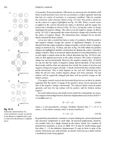
that lack of a centre of symmetry is a necessary condition. Take for example
the symmetric cubic structure shown in Fig. 10.15(a). The positive atoms are
+ – +
on the corner of a square highlighted on Fig. 10.15(b). When a tensile stress
is applied in the vertical direction the lattice is distorted, and the square has
– + –
turned into a rhombus as shown in Fig. 10.15(c), leaving the centre of charge
unchanged for positive charge. The same is true for negative charge, as shown
(b)
+ in Fig. 10.15(d). Consequently, the centre of positive charge still coincides with
the centre of negative charge. The dimensions have changed but no electric
dipole moment has been created.
+ +
Let us now take a crystal that lacks a centre of symmetry. Both the positive
and negative charges occupy the corners of equilateral triangles. In its un-
+ stressed form the centre of positive charge coincides with the centre of negative
charge as shown in Fig. 10.16(a), and also in Fig. 10.16(b) where the positive
(c) charges are highlighted and the construction for finding the centre of positive
Applied force charge is shown. There is no electric dipole moment (it is not ferroelectric). Let
+ us next apply a tensile stress in the vertical direction (see Fig. 10.16(c)) sim-
ilarly to that applied previously to the cubic structure. The centre of positive
charge has moved downwards. However, for negative charges (Fig. 10.16(d))
+ + we can see that the centre of negative charge moved upwards. If one moved
downwards, and the other one upwards then clearly the centres of positive and
negative charges no longer coincide. A dipole moment has been created which
+ points downwards. This is what happens in one unit cell. Summarizing the
Applied force effect for all unit cells, mobile negative charge will move upwards. The top
surface will be negatively charged and there will be positive charge on the
bottom surface.
If we apply a tensile stress in the horizontal direction we can show by similar
(d)
Applied force argument that the centre of charge of the positive atoms moves upwards and
– – that of the negative charges, downwards. The induced dipole moment points
upwards, and now the top surface will be positive and the bottom surface
negative.
– For small deformations and small electric fields the relationships are linear.
The original relationship between dielectric displacement and electric field D =
εE modifies now to
– –
D = εE + eS, (10.69)
Applied force
where e is the piezoelectric constant. Similarly, Hooke’s law, T = cS (T is
Fig. 10.15 stress, c is the elastic constant, and S is strain) modifies to
Schematic representation of a
centro-symmetric crystal: (a) and (b) T = cS – εE . (10.70)
in the absence of applied stress, and
(c) and (d) in the presence of applied In general the piezoelectric constant is a tensor relating the various mechanical
stress. and electrical components to each other. In practical applications, however,
one usually relies on a single element in the tensor, which, for a number of
piezoelectric materials, is given in Table 10.3. It may be worth noting again
that when E = 0, the dielectric displacement, D, may be finite in spite of the
electric field being zero and similarly, an electric field sets up a strain without
a mechanical stress being applied.