
Page 367 - Electrical Properties of Materials
P. 367
Volume holography and phase conjugation 349
may occur quickly (it is in a range extending from nanoseconds to seconds) we
have here a real-time holographic material.
In fact, the major application of photorefractive materials is not for real-time
holography but for wave interaction. The phenomenon by which the incident
light brings forth a dielectric constant modulation and the way this modulation
reacts back (by diffracting the waves) upon the light beams, leads to all sorts
of interesting effects. I shall mention only the most notable one among them,
phase conjugation.
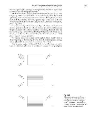
The physical configuration is shown in Fig. 13.9. There are three beams
incident upon the material, and a fourth beam is generated. For this reason
the phenomenon is often referred to as four-wave mixing. Beams 1 and 2 are
known as the pump beams and beam 4 as the probe beam (usually much weaker
than the pump beams). As a result of the interaction, beam 3, the so-called
phase conjugate beam, is generated.
The physical mechanism is fairly easy to explain. Beams 1 and 4 create a
dielectric grating, as shown in Fig. 13.9(b). Beam 2, incident upon the grating,
is then diffracted to produce beam 3, as shown in Fig. 13.9(c).
What is so interesting about beam 3? Well, it is in a direction opposite to
beam 4, but there is a lot more to it. If beam 4 consists of a range of plane
beam 2
beam 3
beam 4
beam 1 (a)
beam 4
beam 1 (b)
Fig. 13.9
beam 2 Schematic representation of phase
beam 3
conjugation. (a) Incident beams 1, 2,
and 4 produce the phase conjugate
beam 3. (b) Beams 1 and 4 produce
a grating. (c) Beam 2 is diffracted into
(c) beam 3 by the grating recorded.