
Page 368 - Electrical Properties of Materials
P. 368
350 Optoelectronics
Conventional
1 4 mirror
2 3
dielectric
(a)
1 4 2 3
Phase
dielectric conjugate
mirror
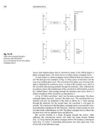
Fig. 13.10
Plane waves passing through a
dielectric and reflected by
(a) a conventional mirror, (b) a phase
conjugate mirror. (b)
waves, each separate plane wave is reversed to create, in the official jargon, a
phase conjugate beam. The whole device is called a phase conjugate mirror.
In what respect is a phase conjugate mirror different from an ordinary mir-
ror? We shall give two examples. In Fig. 13.10(a) a piece of dielectric is in the
way of an incident plane wave. The wavefront of the plane wave moving to the
right is illustrated by continuous lines: 1 is that of the incident wave, and 2 is
the wavefront after passing partially through the dielectric. After reflection by
an ordinary mirror, the retarded part of the wavefront is still retarded, as given
by 3 (dotted lines). After passing through the dielectric once more, there is a
further retardation of the wavefront, as indicated by 4.
In Fig. 13.10(b) wavefronts 1 and 2 are the same as previously. The phase
conjugate mirror, however, ‘reverses’ the input wave. The wavefront that was
retarded will now be promoted to the front as shown by 3. After passing
through the dielectric for the second time, the wavefront 4 will again be
smooth. The conclusion is that the phase conjugate mirror corrected the wave-
front distortion introduced by the dielectric. And this would actually be true
for other kinds of disturbances as well. The phase conjugate mirror reflects the
incident wave with an opposite phase and direction.
My second example is a beam diverging towards the mirror. After
reflection the conventional mirror will make the beam diverge further
[Fig. 13.11(a)] whereas the phase conjugate mirror will produce a convergent
wave [Fig. 13.11(b)]. A fascinating phenomenon you must agree but, I am
afraid, still at the laboratory stage.