
Page 373 - Electrical Properties of Materials
P. 373
Integrated optics 355
2πL n
φ = . (13.12) L is the length of the electrodes.
λ
A voltage of 5 V with a distance of 5 μm between the electrodes gives an
6
electric field of 10 Vm –1 for which we found previously (Section 13.4)
–4
n =1.86 × 10 . A little algebra will then tell us that in order to produce
a phase difference of π at a wavelength of about 1.5 μ m (good for optical
communications) we need electrode lengths of about 4 mm. So we have now a
phase shifter, or if we keep on varying the voltage between 0 and 5 V, we have
a phase modulator.
13.7.3 Directional coupler
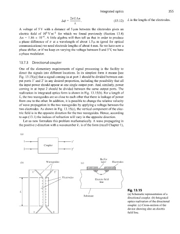
One of the elementary requirements of signal processing is the facility to
direct the signals into different locations. In its simplest form it means [see
Fig. 13.15(a)] that a signal coming in at port 1 should be divided between out-
put ports 1 and 2 in any desired proportion, including the possibility that all
the input power should appear at one single output port. And, similarly, power
coming in at input 2 should be divided between the same output ports. The
realization in integrated optics form is shown in Fig. 13.15(b). For a length of
L, the two waveguides are so close to each other that there is leakage of power
from one to the other. In addition, it is possible to change the relative velocity
of wave propagation in the two waveguides by applying a voltage between the
two electrodes. As shown in Fig. 13.15(c), the vertical component of the elec-
tric field is in the opposite direction for the two waveguides. Hence, according
to eqn (13.1) the indices of refraction will vary in the opposite direction.
Let us now formulate this problem mathematically. A wave propagating in
the positive z-direction with a wavenumber k 1 is of the form (recall Chapter 1),
(a)
1 1
Coupler
2 2
Buffer
(b) Waveguides (c) layer Electrodes
1 2
Electrodes
Electric field
line
Fig. 13.15
L
(a) Schematic representation of a
Substrate
directional coupler. (b) Integrated
optics realization of the directional
coupler. (c) Cross-section of the
device showing also an electric
1 2 field line.