
Page 375 - Electrical Properties of Materials
P. 375
Spatial light modulators 357
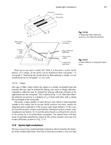
Electrode
Corrugation
L Waveguide
λg
2 Fig. 13.16
A Bragg type filter employing
W
0 grooves as the reflecting elements.
Input prism Y-cut LiNbO 3
coupler waveguide
Incident
light Bragg diffracted
beam light beam
Acoustic Output prism
transducers coupler
Fig. 13.17
Undiffracted A beam deflector in Integrated Optics
light beam form.
What can we use such a coupler for? Well, it is obviously a switch. In the
absence of a voltage, all the power can be transferred from waveguide 1 to
waveguide 2. Destroying the synchronism by then applying a voltage, we can
switch the power to waveguide 1 or vice versa.
13.7.4 Filters
One type of filter, which reflects the signal in a certain wavelength band and
transmits the rest, may be realized by relying once more on Bragg reflection.
Cumulative reflection may be obtained by placing reflecting elements at the
right period into the waveguide. This is shown in Fig. 13.16, where the reflect-
ing elements are grooves at a distance of λ g /2 from each other, with λ g being
the wavelength in the waveguide.
Obviously, a large number of other devices exist which I cannot possibly
include in this course, but let me just briefly mention one more, namely the
integrated optics realization of the acousto-optic beam deflector. In this case,
the steerable acoustic column is provided by interdigital surface acoustic wave
transducers (see Section 10.13) and the optical beam is confined to the vicinity
of the surface by a so-called planar waveguide. The optical beam will then
sense the periodic perturbation caused by the surface acoustic wave and will
be duly diffracted, as shown in Fig. 13.17.
13.8 Spatial light modulators
We have several times mentioned light modulators which modulate the intens-
ity of the incident light beam. Note that in those devices there is only one light