
Page 377 - Electrical Properties of Materials
P. 377
Nonlinear Fabry–Perot cavities 359
We have already mentioned the quest for a liquid crystal display in Sec-
tion 10.15. The ideal device that still needs to be produced is a spatial light
modulator which is voltage addressable with a resolution of the order of a
wavelength and a speed (say nanoseconds) comparable with that of fast digital
computers.
13.9 Nonlinear Fabry–Perot cavities
A number of interesting effects occur when either the absorption coefficient or
the dielectric constant depend on the intensity of light. In this section we shall
discuss one particular manifestation of this nonlinear effect when a dielectric,
whose index of refraction obeys eqn (13.4), forms a Fabry–Perot cavity.
It is fairly easy to show that the relationship between I t , and I i , the output
and input intensity of the cavity, is
–1
I t 4R 2
= 1+ sin kl , (13.20)
I i (1 – R) 2
where l is the length of the cavity, k is the wavenumber, and R is the power
reflection coefficient. Equation (13.20) makes good sense. When kl = mπ or
l = mλ/2, the transmission is maximum (all power is transmitted), whereas
minimum transmission occurs when kl =2(m +1)(π/2), or l =(2m +1)(λ/4).
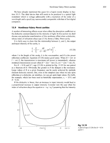
For R = 0.36 and 0.7, eqn (13.20) is plotted in Fig. 13.19 for one period
as a function of kl. Obviously, the greater is R the sharper is the resonance.
Large values of R at a given frequency can be easily achieved by multiple
element dielectric mirrors. But, even in the simplest case when we rely upon
reflection at a dielectric–air interface, we can get quite high values. For InSb,
for example, which has been used in bistability experiments, r = 15.9, and
R = 0.36.
If the dielectric is linear, then an increase in input intensity would lead to
a proportional increase in output intensity. Consider now the case when the
index of refraction obeys the equation n = n 0 +n 2 I (assuming that the intensity
1
I B
t
I A
i
R = 0.36
0.5
R = 0.7
Fig. 13.19
0
mπ (2m+1) π kl (m+1)π A plot of eqn (13.20) for R = 0.36
2 and 0.7.