
Page 378 - Electrical Properties of Materials
P. 378
360 Optoelectronics
inside the cavity is the same as that leaving) and take a point on the I t /I i curve,
where the function is increasing (A in Fig. 13.19). What happens now if I i is
increased? Then first, we may argue, I t will increase as in the linear regime.
But an increase in I t will lead to an increase in n and k, and consequently, we
need to move up to a point higher on the curve, say B. But this means that, for
agiven valueof I i , we have an even higher value of I t , which increases n even
further, and in turn makes us move higher up on the curve, etc. Because of this
positive feedback, a small increase in I i may lead to a large increase in I t .So
the I t versus I i curve may turn out to be highly nonlinear.
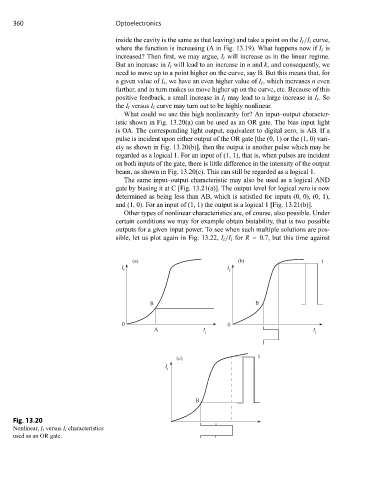
What could we use this high nonlinearity for? An input–output character-
istic shown in Fig. 13.20(a) can be used as an OR gate. The bias input light
is OA. The corresponding light output, equivalent to digital zero, is AB. If a
pulse is incident upon either output of the OR gate [the (0, 1) or the (1, 0) vari-
ety as shown in Fig. 13.20(b)], then the output is another pulse which may be
regarded as a logical 1. For an input of (1, 1), that is, when pulses are incident
on both inputs of the gate, there is little difference in the intensity of the output
beam, as shown in Fig. 13.20(c). This can still be regarded as a logical 1.
The same input–output characteristic may also be used as a logical AND
gate by biasing it at C [Fig. 13.21(a)]. The output level for logical zero is now
determined as being less than AB, which is satisfied for inputs (0, 0), (0, 1),
and (1, 0). For an input of (1, 1) the output is a logical 1 [Fig. 13.21(b)].
Other types of nonlinear characteristics are, of course, also possible. Under
certain conditions we may for example obtain bistability, that is two possible
outputs for a given input power. To see when such multiple solutions are pos-
sible, let us plot again in Fig. 13.22, I t /I i for R = 0.7, but this time against
(a) (b) 1
I I
t t
B B
0 0
A I I
i i
(c) 1
I
t
B
Fig. 13.20
Nonlinear, I t versus I i characteristics
used as an OR gate.