
Page 279 - Electromagnetics
P. 279
10
9
8
7 β
ω/2≠ (MHz) 6 Light Line
5
4
3
2
α
1
0
0.00 0.02 0.04 0.06 0.08 0.10 0.12 0.14 0.16 0.18 0.20 0.22
or α (1/m)
11
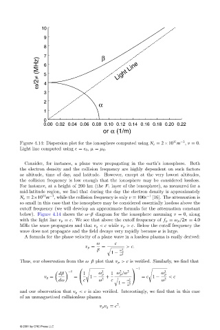
Figure 4.14: Dispersion plot for the ionosphere computed using N e = 2×10 m −3 , ν = 0.
Light line computed using = 0 , µ = µ 0 .
Consider, for instance, a plane wave propagating in the earth’s ionosphere. Both
the electron densityand the collision frequencyare highlydependent on such factors
as altitude, time of day, and latitude. However, except at the very lowest altitudes,
the collision frequencyis low enough that the ionosphere maybe considered lossless.
For instance, at a height of 200 km (the F 1 layer of the ionosphere), as measured for a
mid-latitude region, we find that during the daythe electron densityis approximately
11
N e = 2×10 m −3 , while the collision frequencyis only ν = 100s −1 [16]. The attenuation is
so small in this case that the ionosphere maybe considered essentiallylossless above the
cutoff frequency(we will develop an approximate formula for the attenuation constant
below). Figure 4.14 shows the ω–β diagram for the ionosphere assuming ν = 0, along
with the light line v p = c. We see that above the cutoff frequencyof f p = ω p /2π = 4.0
MHz the wave propagates and that v g < c while v p > c. Below the cutoff frequencythe
wave does not propagate and the field decays very rapidly because α is large.
A formula for the phase velocityof a plane wave in a lossless plasma is easilyderived:
ω c
v p = = > c.
β ω p 2
1 −
ω 2
Thus, our observation from the ω–β plot that v p > c is verified. Similarly, we find that
−1
−1 2 2
dβ 1 ω p 1 ω /ω ω p
2 2
p
v g = = 1 − + = c 1 − < c
dω c ω 2 c ω p 2 ω 2
1 −
ω 2
and our observation that v g < c is also verified. Interestingly, we find that in this case
of an unmagnetized collisionless plasma
2
v p v g = c .
© 2001 by CRC Press LLC