
Page 292 - Electromagnetics
P. 292
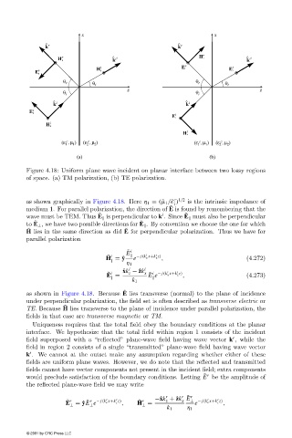
Figure 4.18: Uniform plane wave incident on planar interface between two lossyregions
                        of space. (a) TM polarization, (b) TE polarization.


                                                                       c 1/2
                        as shown graphicallyin Figure 4.18. Here η 1 = ( ˜µ 1 /˜  )  is the intrinsic impedance of
                                                                       1
                                                                      ˜
                        medium 1. For parallel polarization, the direction of E is found byremembering that the
                                                                           ˜
                                               ˜
                                                                   i
                        wave must be TEM. Thus E   is perpendicular to k . Since E   must also be perpendicular
                          ˜
                                                            ˜
                        to E ⊥ , we have two possible directions for E   . Byconvention we choose the one for which
                                                       ˜
                        ˜
                        H lies in the same direction as did E for perpendicular polarization. Thus we have for
                        parallel polarization
                                                        ˜ i
                                                        E     i  i
                                                  ˜ i
                                                          e
                                                 H = ˆ y    − j(k x x+k z z) ,                (4.272)

                                                        η 1
                                                         i
                                                       ˆ xk − ˆ zk i  i  i
                                                  ˜ i    z    x  ˜ i − j(k x x+k z z)
                                                  E =          E e        ,                   (4.273)

                                                          k 1
                                                       ˜
                        as shown in Figure 4.18. Because  E  lies transverse (normal) to the plane of incidence
                        under perpendicular polarization, the field set is often described as transverse electric or
                                    ˜
                        TE. Because H lies transverse to the plane of incidence under parallel polarization, the
                        fields in that case are transverse magnetic or TM.
                          Uniqueness requires that the total field obeythe boundaryconditions at the planar
                        interface. We hypothesize that the total field within region 1 consists of the incident
                                                                                          r
                        field superposed with a “reflected” plane-wave field having wave vector k , while the
                        field in region 2 consists of a single “transmitted” plane-wave field having wave vector
                         t
                        k . We cannot at the outset make anyassumption regarding whether either of these
                        fields are uniform plane waves. However, we do note that the reflected and transmitted
                        fields cannot have vector components not present in the incident field; extra components
                                                                                 ˜ r
                        would preclude satisfaction of the boundaryconditions. Letting E be the amplitude of
                        the reflected plane-wave field we maywrite
                                                                    r
                                                                          r ˜ r
                                                                 −ˆ xk + ˆ zk E ⊥ − j(k x x+k z z)
                                                    r
                                                                                     r
                                                                                  r
                                                 r
                                                                          x
                                     ˜ r
                                                                    z
                                                            ˜ r
                                              − j(k x x+k z z)
                                           ˜ r
                                    E = ˆ yE e        ,    H =                e        ,
                                      ⊥     ⊥                ⊥
                                                                     k 1   η 1
                        © 2001 by CRC Press LLC