
Page 305 - Electromagnetics
P. 305
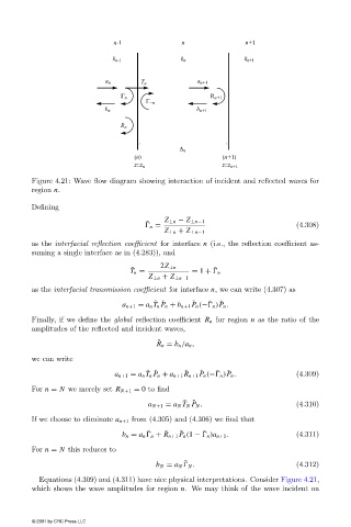
Figure 4.21: Wave flow diagram showing interaction of incident and reflected waves for
                        region n.

                        Defining
                                                      ˜    Z ⊥n − Z ⊥n−1
                                                        n =                                   (4.308)
                                                           Z ⊥n + Z ⊥n−1
                        as the interfacial reflection coefficient for interface n (i.e., the reflection coefficient as-
                        suming a single interface as in (4.283)), and

                                                  ˜       2Z ⊥n         ˜
                                                  T n =           = 1 +   n
                                                       Z ⊥n + Z ⊥n−1
                        as the interfacial transmission coefficient for interface n, we can write (4.307) as

                                                                       ˜
                                                         ˜ ˜
                                                                   ˜
                                                                          ˜
                                                a n+1 = a n T n P n + b n+1 P n (−  n )P n .
                        Finally, if we define the global reflection coefficient R n for region n as the ratio of the
                        amplitudes of the reflected and incident waves,
                                                         ˜
                                                         R n = b n /a n ,
                        we can write
                                                                         ˜
                                                                            ˜
                                                                 ˜
                                                      ˜ ˜
                                                                     ˜
                                              a n+1 = a n T n P n + a n+1 R n+1 P n (−  n )P n .  (4.309)
                        For n = N we merelyset R N+1 = 0 to find
                                                                ˜ ˜
                                                       a N+1 = a N T N P N .                  (4.310)
                        If we choose to eliminate a n+1 from (4.305) and (4.306) we find that
                                                                      ˜
                                                           ˜
                                                       ˜
                                                               ˜
                                                b n = a n   n + R n+1 P n (1 −   n )a n+1 .   (4.311)
                        For n = N this reduces to
                                                                ˜
                                                         b N = a N   N .                      (4.312)
                          Equations (4.309) and (4.311) have nice physical interpretations. Consider Figure 4.21,
                        which shows the wave amplitudes for region n. We maythink of the wave incident on


                        © 2001 by CRC Press LLC