
Page 308 - Electromagnetics
P. 308
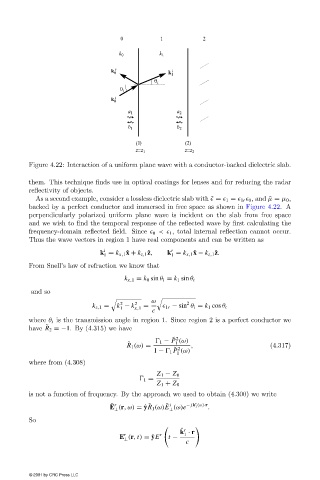
Figure 4.22: Interaction of a uniform plane wave with a conductor-backed dielectric slab.

                        them. This technique finds use in optical coatings for lenses and for reducing the radar
                        reflectivityof objects.
                          As a second example, consider a lossless dielectric slab with ˜  =   1  =   1r   0 , and  ˜µ = µ 0 ,
                        backed by a perfect conductor and immersed in free space as shown in Figure 4.22. A
                        perpendicularlypolarized uniform plane wave is incident on the slab from free space
                        and we wish to find the temporal response of the reflected wave byfirst calculating the
                        frequency-domain reflected field. Since   0 <  1 , total internal reflection cannot occur.
                        Thus the wave vectors in region 1 have real components and can be written as
                                              i
                                                                 r
                                             k = k x,1 ˆ x + k z,1 ˆ z,  k = k x,1 ˆ x − k z,1 ˆ z.
                                              1                  1
                        From Snell’s law of refraction we know that
                                                    k x,1 = k 0 sin θ i = k 1 sin θ t
                        and so
                                                            ω         2

                                                   2
                                                       2
                                          k z,1 =  k − k  =
                                                  1    x,1       1r − sin θ i = k 1 cos θ t
                                                            c
                        where θ t is the transmission angle in region 1. Since region 2 is a perfect conductor we
                             ˜
                        have R 2 =−1. By(4.315) we have
                                                                  ˜ 2
                                                               1 − P (ω)
                                                     ˜             1
                                                    R 1 (ω) =          ,                      (4.317)
                                                                  ˜ 2
                                                            1 −   1 P (ω)
                                                                   1
                        where from (4.308)
                                                             Z 1 − Z 0
                                                          1 =
                                                             Z 1 + Z 0
                        is not a function of frequency. By the approach we used to obtain (4.300) we write
                                                                        r
                                                           ˜
                                                                ˜ i
                                                ˜ r
                                                E (r,ω) = ˆ yR 1 (ω)E (ω)e − jk (ω)·r .
                                                                        1
                                                 ⊥               ⊥
                        So

                                                                    ˆ r
                                                                    k · r
                                                              r
                                                                     1
                                                    r
                                                  E (r, t) = ˆ yE  t −
                                                    ⊥
                                                                      c
                        © 2001 by CRC Press LLC