
Page 310 - Electromagnetics
P. 310
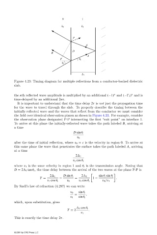
Figure 4.23: Timing diagram for multiple reflections from a conductor-backed dielectric
                        slab.

                                                                                              n
                                                                                   n
                        the nth reflected wave amplitude is multiplied byan additional (−1) and (−  1 ) and is
                        time-delayed by an additional 2nτ.
                          It is important to understand that the time delay 2τ is not just the propagation time
                        for the wave to travel through the slab. To properlydescribe the timing between the
                        initially-reflected wave and the waves that reflect from the conductor we must consider
                        the field over identical observation planes as shown in Figure 4.23. For example, consider
                        the observation plane designated P-P intersecting the first “exit point” on interface 1.
                        To arrive at this plane the initially-reflected wave takes the path labeled B, arriving at
                        a time
                                                           D sin θ i
                                                             v 0
                        after the time of initial reflection, where v 0 = c is the velocityin region 0. To arrive at
                        this same plane the wave that penetrates the surface takes the path labeled A, arriving
                        at a time

                                                            2  1
                                                           v 1 cos θ t
                        where v 1 is the wave velocityin region 1 and θ t is the transmission angle. Noting that
                        D = 2  1 tan θ t , the time delaybetween the arrival of the two waves at the plane P-P is

                                             2  1    D sin θ i  2  1      sin θ t sin θ i
                                       T =         −        =          1 −          .
                                           v 1 cos θ t  v 0   v 1 cos θ t   v 0 /v 1
                        BySnell’s law of refraction (4.297) we can write

                                                         v 0  sin θ i
                                                            =      ,
                                                         v 1  sin θ t
                        which, upon substitution, gives

                                                               1 cos θ t
                                                       T = 2        .
                                                               v 1
                        This is exactlythe time delay 2τ.


                        © 2001 by CRC Press LLC