
Page 123 - Electromechanical Devices and Components Illustrated Sourcebook
P. 123
Chapter 5 Magnetic Components 85
Transformers The output voltage of a transformer is a function of the
ratio of the number of windings of the primary to the sec-
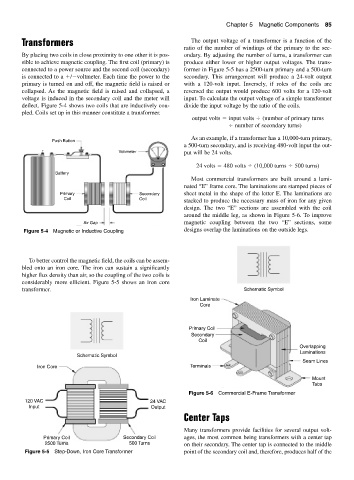
By placing two coils in close proximity to one other it is pos- ondary. By adjusting the number of turns, a transformer can
sible to achieve magnetic coupling. The first coil (primary) is produce either lower or higher output voltages. The trans-
connected to a power source and the second coil (secondary) former in Figure 5-5 has a 2500-turn primary and a 500-turn
is connected to a / voltmeter. Each time the power to the secondary. This arrangement will produce a 24-volt output
primary is turned on and off, the magnetic field is raised or with a 120-volt input. Inversely, if roles of the coils are
collapsed. As the magnetic field is raised and collapsed, a reversed the output would produce 600 volts for a 120-volt
voltage is induced in the secondary coil and the meter will input. To calculate the output voltage of a simple transformer
deflect. Figure 5-4 shows two coils that are inductively cou- divide the input voltage by the ratio of the coils.
pled. Coils set up in this manner constitute a transformer.
output volts input volts (number of primary turns
number of secondary turns)
As an example, if a transformer has a 10,000-turn primary,
Push Button
a 500-turn secondary, and is receiving 480-volt input the out-
+ − Voltmeter put will be 24 volts.
24 volts 480 volts (10,000 turns 500 turns)
Battery
Most commercial transformers are built around a lami-
nated “E” frame core. The laminations are stamped pieces of
Primary Secondary sheet metal in the shape of the letter E. The laminations are
Coil Coil stacked to produce the necessary mass of iron for any given
design. The two “E” sections are assembled with the coil
around the middle leg, as shown in Figure 5-6. To improve
Air Gap magnetic coupling between the two “E” sections, some
Figure 5-4 Magnetic or Inductive Coupling designs overlap the laminations on the outside legs.
To better control the magnetic field, the coils can be assem-
bled onto an iron core. The iron can sustain a significantly
higher flux density than air, so the coupling of the two coils is
considerably more efficient. Figure 5-5 shows an iron core
transformer. Schematic Symbol
Iron Laminate
Core
Primary Coil
Secondary
Coil
Overlapping
Laminations
Schematic Symbol
Seam Lines
Iron Core Terminals
Mount
Tabs
Figure 5-6 Commercial E-Frame Transformer
120 VAC 24 VAC
Input Output
Center Taps
Many transformers provide facilities for several output volt-
Primary Coil Secondary Coil ages, the most common being transformers with a center tap
2500 Turns 500 Turns on their secondary. The center tap is connected to the middle
Figure 5-5 Step-Down, Iron Core Transformer point of the secondary coil and, therefore, produces half of the