
Page 124 - Electromechanical Devices and Components Illustrated Sourcebook
P. 124
86 Electromechanical Devices & Components Illustrated Sourcebook
Schematic Symbol
Schematic Symbol
120-Volt Output
Input Output Fuse
Terminals Secondary
Input Fuses Terminals
Primary
Terminals
Secondary 480-Volt
Terminals
Jumper
Center Tap
Mount Tabs
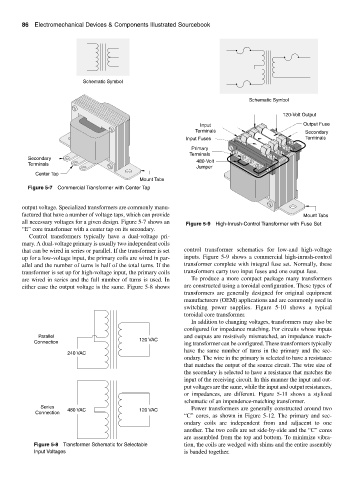
Figure 5-7 Commercial Transformer with Center Tap
output voltage. Specialized transformers are commonly manu-
factured that have a number of voltage taps, which can provide Mount Tabs
all necessary voltages for a given design. Figure 5-7 shows an Figure 5-9 High-Inrush-Control Transformer with Fuse Set
“E” core transformer with a center tap on its secondary.
Control transformers typically have a dual-voltage pri-
mary. A dual-voltage primary is usually two independent coils
that can be wired in series or parallel. If the transformer is set control transformer schematics for low-and high-voltage
up for a low-voltage input, the primary coils are wired in par- inputs. Figure 5-9 shows a commercial high-inrush-control
allel and the number of turns is half of the total turns. If the transformer complete with integral fuse set. Normally, these
transformer is set up for high-voltage input, the primary coils transformers carry two input fuses and one output fuse.
are wired in series and the full number of turns is used. In To produce a more compact package many transformers
either case the output voltage is the same. Figure 5-8 shows are constructed using a toroidal configuration. These types of
transformers are generally designed for original equipment
manufacturers (OEM) applications and are commonly used in
switching power supplies. Figure 5-10 shows a typical
toroidal core transformer.
In addition to changing voltages, transformers may also be
configured for impedance matching. For circuits whose inputs
Parallel and outputs are resistively mismatched, an impedance match-
Connection 120 VAC ing transformer can be configured. These transformers typically
have the same number of turns in the primary and the sec-
240 VAC
ondary. The wire in the primary is selected to have a resistance
that matches the output of the source circuit. The wire size of
the secondary is selected to have a resistance that matches the
input of the receiving circuit. In this manner the input and out-
put voltages are the same, while the input and output resistances,
or impedances, are different. Figure 5-11 shows a stylized
schematic of an impendence-matching transformer.
Series 480 VAC Power transformers are generally constructed around two
Connection 120 VAC
“C” cores, as shown in Figure 5-12. The primary and sec-
ondary coils are independent from and adjacent to one
another. The two coils are set side-by-side and the “C” cores
are assembled from the top and bottom. To minimize vibra-
Figure 5-8 Transformer Schematic for Selectable tion, the coils are wedged with shims and the entire assembly
Input Voltages is banded together.