
Page 128 - Electromechanical Devices and Components Illustrated Sourcebook
P. 128
90 Electromechanical Devices & Components Illustrated Sourcebook
Internal Cables
Lifting Terminal Box Primary
Eyes Power Lines
Primary
Clamp Terminals
Frame
High-Voltage
Input
Cap
Pole
Coil Center Tap
Secondary
Sets
Pole Clamp Terminals
Steel Case
Pole Hook Common
Cable Grip
Mount Power Drops
Feet Pole Ground
Figure 5-24 Large Three-Phase Power Distribution
Transformer
Figure 5-25 Pole Transformer
depending on the requirements of the specific application.
Figure 5-24 shows a large three-phase power distribution
transformer. Transformers like this are generally immersed in
a high dielectric oil to improve insulation and cooling. Larger Secondary Terminal
units may have forced air heat exchangers as an integral part
of the overall assembly. Common Terminal Primary Terminal
Most of us have noticed the pole transformers that dot our
community. These are typically power transformers immersed
in high dielectric oil. The steel case is designed to provide a Cap Case Crimp
high level of protection against almost any weather condi-
tion. It is common to find these transformers providing excel-
lent service even 50 years after they had been installed. The
large terminals on the top are the primary and the side termi-
nals are the secondary. The secondary typically has a center Secondary Coil Core
tap, which is connected to ground. Figure 5-25 shows a typ-
ical single-phase pole transformer and associated wiring. Primary Coil
Note that the center tap of the secondary is connected to the
common leg, which is grounded at the pole as well as the Case
building it is serving.
Potting
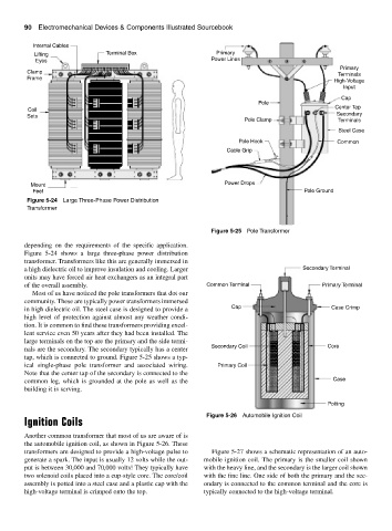
Figure 5-26 Automobile Ignition Coil
Ignition Coils
Another common transformer that most of us are aware of is
the automobile ignition coil, as shown in Figure 5-26. These
transformers are designed to provide a high-voltage pulse to Figure 5-27 shows a schematic representation of an auto-
generate a spark. The input is usually 12 volts while the out- mobile ignition coil. The primary is the smaller coil shown
put is between 30,000 and 70,000 volts! They typically have with the heavy line, and the secondary is the larger coil shown
two solenoid coils placed into a cup-style core. The core/coil with the fine line. One side of both the primary and the sec-
assembly is potted into a steel case and a plastic cap with the ondary is connected to the common terminal and the core is
high-voltage terminal is crimped onto the top. typically connected to the high-voltage terminal.