
Page 132 - Electromechanical Devices and Components Illustrated Sourcebook
P. 132
94 Electromechanical Devices & Components Illustrated Sourcebook
Area of 400 Hz Wave
is 0.15 of 60 Hz Wave
N
Zero Volts Zero Volts
Field Lines
1/60 Second 1/60 Second
S
60 Hz 400 Hz
Total Combined Area for
1/60 Second is Equal Figure 5-41 Horseshoe Magnet and Field
Figure 5-38 Effects of Frequency on Core Mass Lines
Figure 5-39 shows a size comparison between a 60 Hz and
a 400 Hz transformer with the same voltage and current car- Electromagnets
rying capabilities. More often then not, the size of a high fre-
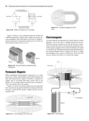
An electromagnet can be produced by simply feeding a current
quency transformer is dictated by the physical size of the coil
through a coil of wire that is wrapped around an iron bar.
and terminals instead of the core size.
When the current is turned on, the iron bar becomes magne-
tized, and when the current is turned off, the magnetism is lost.
In this manner a magnet can be constructed that may be turned
on and off at will. This phenomenon has profound implications
for electromechanical devices. Figure 5-42 shows a simple
electromagnet, power source, and field lines. Notice the field
lines are similar to the lines of a common bar magnet.
400 Hz
60 Hz Coil
Figure 5-39 60 Hz and 400 Hz Transformer Size Iron Core
Comparison
Field Lines
Permanent Magnets
When considering electromagnetic components, it’s a good
idea to have a basic understanding of permanent magnets and
their field characteristics. Figure 5-40 shows a common bar
magnet and its associated field lines. Notice that in the
absence of any outside influences the field lines are balanced.
This is the natural state of the magnet.
Figure 5-41 shows a horseshoe magnet and associated field
lines. Like the bar magnet the field lines are balanced between
the poles, except the flux density is higher because the pole −
spacing is less. +
Field Lines Push Button
Battery
N S
Figure 5-40 Flat Bar Magnet and Field Lines Figure 5-42 Electromagnet