
Page 137 - Electromechanical Devices and Components Illustrated Sourcebook
P. 137
Chapter 5 Magnetic Components 99
Inductors
An inductor is a device that is intended to limit current based
on the rise and collapse of a magnetic field. Most inductors
are coils of wire and any coil is an inductor. Transformers,
solenoids, motors, and the coiled filament of a light bulb are
all inductors. Inductors are rather simple in operation. An AC Schematic Symbol
signal is sent through the coil and an oscillating magnetic
field is set up. As the field rises and collapses, it induces cur-
rents back into the coil that are out of phase with the line signal.
These out-of-phase currents cancel out a part of the line signal
and, in effect, change the resistance of the coil. As the resistance
Terminals
of the coil rises, less current can pass. The unit of measure for
an inductor is the hennery and inductors are generally found Core
rated in milli-henneries. Coil
Figure 5-60 shows a common air core inductor. These
devices are simply a coil of wire wrapped onto a coil form.
Much like transformers, inductors can benefit from magnetic
cores. Figure 5-61 shows a common iron core inductor design
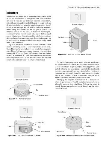
with a solid “C” frame. Figure 5-62 shows an iron core induc-
Figure 5-62 Iron Core Inductor with “E” Frame
tor with a laminated “E” core. The laminations are used to
limit eddy current losses within the core. Notice that this unit
is very similar in appearance to a typical transformer.
To further limit eddycurrent losses, sintered metal cores
are manufactured from ferrite. In this process powdered metal
is cold welded into shapes through a pressing process. Each
particle of metal has an extremely short electrical path and,
therefore, eddy current losses are extremely low. Ferrite-core
inductors are commonly found in high-frequency circuits.
Figure 5-63 shows a typical ferrite core inductor, while
Figure 5-64 shows an exploded view of the unit.
Schematic Symbol Changing the magnetic characteristics of an inductor will
affect its performance. Tunable inductors typically have an
adjustable core, as shown in Figure 5-65. As the screw is
Coil Form
turned, the core moves in and out of the coil and the induc-
tance is affected.
Coil
Terminal Wires
Figure 5-60 Air Core Inductor
Schematic Symbol
Clamp Screw
Schematic Symbol
Coil Form Core
Core Coil Wire Slot
Terminal Wires Mount Stud
Terminal Wires
Figure 5-61 Iron Core Inductor with “C” Frame Figure 5-63 Ferrite Core Inductor with Toroidal Frame