
Page 135 - Electromechanical Devices and Components Illustrated Sourcebook
P. 135
Chapter 5 Magnetic Components 97
Laminated "E" Core 100
Laminated "T"
Percent of Max. Force 50
Plunger
Rivets 75
Bolt Lug Terminals
Coil 25
0
0 20 40 60 80 100
Mounting Flanges
Percent of Max. Extension
Figure 5-50 Laminated Core AC Solenoid
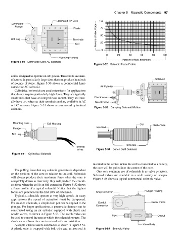
Figure 5-52 Solenoid Force Profile
coil is designed to operate on AC power. These units are man-
ufactured in particularly large sizes that can produce hundreds Solenoid
of pounds of force. Figure 5-50 shows a commercial lami-
nated core AC solenoid. Air Cylinder
Cylindrical solenoids are used extensively for applications
that do not require particularly high force. They are typically
small units that have an integral nose mount. They will usu- Check Valve
ally have two wires as their terminals and are available in AC Needle Valve
or DC versions. Figure 5-51 shows a commercial cylindrical
Figure 5-53 Damping Solenoid Motion
solenoid.
Mounting Nose Coil Housing Coil
Iron Rod Plastic Tube
Plunger
Bolt Lug
Terminals
Terminal
Wires Figure 5-54 Bench Built Solenoid
Figure 5-51 Cylindrical Solenoid
inserted in the center. When the coil is connected to a battery,
the core will be pulled into the center of the core.
The pulling force that any solenoid generates is dependent
One very common use of solenoids is as valve actuators.
on the position of the core in relation to the coil. Solenoids
Solenoid valves are available in a wide variety of designs.
will always produce their maximum force when the core is
Figure 5-55 shows a typical commercial solenoid valve.
completely drawn in. Inversely, they will produce their weak-
est force when the coil is at full extension. Figure 5-52 shows
a force profile of a typical solenoid. Notice that the highest
forces are generated in the first 20% of extension. Snap On Cover Plunger Housing
Typically, solenoids operate at very high speeds. In many
applications the speed of actuation must be dampened.
For smaller solenoids, a simple dash pot can be applied to the Conduit Coil & Frame
plunger. For larger applications, a pneumatic damper can be Connection
constructed using an air cylinder equipped with check and
needle valves, as shown in Figure 5-53. The needle valve can
Input Output
be used to control the rate at which the solenoid retracts. The
check valve allows the core to extend with no restriction.
A simple solenoid can be constructed as shown in Figure 5-54. Valve Body
A plastic tube is wrapped with bell wire and an iron rod is Figure 5-55 Solenoid Valve