
Page 131 - Electromechanical Devices and Components Illustrated Sourcebook
P. 131
Chapter 5 Magnetic Components 93
High-Voltage Terminal Core Secondary
Insulator Terminals
Label
Case
Primary
Terminals
115/120 VAC, 50/60 Hz Input Terminals Compensation
Coil
Mount Tabs
Mount Tabs
Figure 5-34 Neon Light Transformer
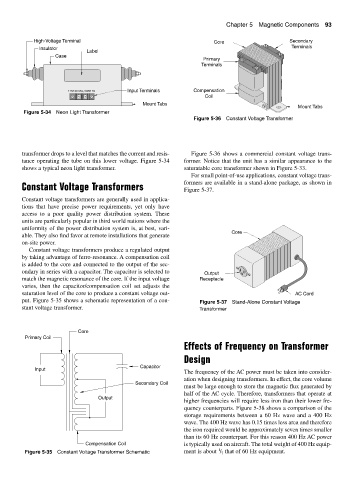
Figure 5-36 Constant Voltage Transformer
transformer drops to a level that matches the current and resis- Figure 5-36 shows a commercial constant voltage trans-
tance operating the tube on this lower voltage. Figure 5-34 former. Notice that the unit has a similar appearance to the
shows a typical neon light transformer. saturatable core transformer shown in Figure 5-33.
For small point-of-use applications, constant voltage trans-
formers are available in a stand-alone package, as shown in
Constant Voltage Transformers Figure 5-37.
Constant voltage transformers are generally used in applica-
tions that have precise power requirements, yet only have
access to a poor quality power distribution system. These
units are particularly popular in third world nations where the
uniformity of the power distribution system is, at best, vari-
Core
able. They also find favor at remote installations that generate
on-site power.
Constant voltage transformers produce a regulated output
by taking advantage of ferro-resonance. A compensation coil
is added to the core and connected to the output of the sec-
ondary in series with a capacitor. The capacitor is selected to Output
match the magnetic resonance of the core. If the input voltage Receptacle
varies, then the capacitor/compensation coil set adjusts the
saturation level of the core to produce a constant voltage out- AC Cord
put. Figure 5-35 shows a schematic representation of a con- Figure 5-37 Stand-Alone Constant Voltage
stant voltage transformer. Transformer
Core
Primary Coil
Effects of Frequency on Transformer
Design
Capacitor
Input
The frequency of the AC power must be taken into consider-
ation when designing transformers. In effect, the core volume
Secondary Coil
must be large enough to store the magnetic flux generated by
half of the AC cycle. Therefore, transformers that operate at
Output
higher frequencies will require less iron than their lower fre-
quency counterparts. Figure 5-38 shows a comparison of the
storage requirements between a 60 Hz wave and a 400 Hz
wave. The 400 Hz wave has 0.15 times less area and therefore
the iron required would be approximately seven times smaller
than its 60 Hz counterpart. For this reason 400 Hz AC power
Compensation Coil is typically used on aircraft. The total weight of 400 Hz equip-
1
Figure 5-35 Constant Voltage Transformer Schematic ment is about / that of 60 Hz equipment.
7