
Page 130 - Electromechanical Devices and Components Illustrated Sourcebook
P. 130
92 Electromechanical Devices & Components Illustrated Sourcebook
Saturatable
Core
Primary Coil
Secondary
Coil
Schematic Symbol
Bridge Adjustment Screw Input Output
Coil Guide
Primary
Terminals
Moving Coil
(Secondary)
Core Fixed Coil
Reactor Coil
Mounts
Control
Secondary Terminals Transformer
Figure 5-30 Moving-Coil Transformer Single Diode
Rheostat
Figure 5-32 Saturatable Transformer Control Schematic
The same current limiting effect can be achieved by mov-
ing one of the coils into a position that will reduce the mag-
netic coupling. Figure 5-30 shows a moving-coil trans- Figure 5-32 shows a schematic representation of a control
former. In this case, the secondary is raised or lowered to circuit that might be used with a saturatable core transformer.
adjust the coupling efficiency and therefore limiting the out- Take note of the simplicity of the circuit. This allows for a
put current. low-cost and robust design which finds favor in the demand-
The second current-limiting method is to electrically induce ing role of electric arc welding supplies.
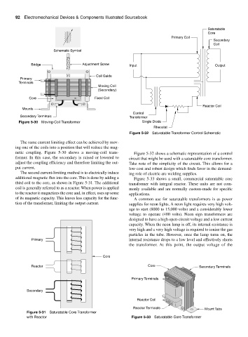
additional magnetic flux into the core. This is done by adding a Figure 5-33 shows a small, commercial saturatable core
third coil to the core, as shown in Figure 5-31. The additional transformer with integral reactor. These units are not com-
coil is generally referred to as a reactor. When power is applied monly available and are normally custom-made for specific
to the reactor it magnetizes the core and, in effect, uses up some applications.
of its magnetic capacity. This leaves less capacity for the func- A common use for saturatable transformers is as power
tion of the transformer, limiting the output current. supplies for neon lights. A neon light requires very high volt-
age to start (8000 to 15,000 volts) and a considerably lower
voltage to operate (400 volts). Neon sign transformers are
designed to have a high open-circuit voltage and a low current
capacity. When the neon lamp is off, its internal resistance is
very high and a very high voltage is required to ionize the gas
particles in the tube. However, once the lamp turns on, the
Primary internal resistance drops to a low level and effectively shorts
the transformer. At this point, the output voltage of the
Core
Reactor Core Secondary Terminals
Primary Terminals
Secondary
Reactor Coil
Reactor Terminals Mount Tabs
Figure 5-31 Saturatable Core Transformer
with Reactor Figure 5-33 Saturatable Core Transformer