
Page 125 - Electromechanical Devices and Components Illustrated Sourcebook
P. 125
Chapter 5 Magnetic Components 87
Isolation Transformers
The transformers discussed thus far are constructed with two
separate coils, therefore the inputs and the outputs are electri-
cally isolated. This type of design is generally referred to as
an isolation transformer and the level of isolation is a function
of the insulation between the coils and/or the core. Usually,
Schematic Symbol the level of isolation is given in volts. Isolation transformers
are particularly useful for electrically detaching a sensitive
application from a noisy power source. The most notable use
of isolation transformers is for home and business power dis-
tribution. Power transformers mounted on the poles electrically
Input
isolate power drops from the distribution grid and therefore
protect homes and businesses from the high-voltage transients
that routinely occur.
Output
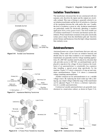
Autotransformers
W/ Center Tap
Autotransformers are a type of transformer that uses only one
Figure 5-10 Toroidal Core Transformer winding. These units do not have an isolation function and
should only be used when isolation is not warranted. These
transformers are generally used for voltage-matching applica-
tions. If a 208 VAC machine must be placed in a location that
only provides access to 240 VAC, an autotransformer can be
placed to step-down the voltage. In most instances the instal-
lation of an autotransformer is considerably less expensive
than installing a special power drop specifically for the
Schematic Symbol
machine. Figure 5-13 shows schematics of step-up and step-
down autotransformers. Figure 5-14 shows a commercial
Iron Core voltage-matching autotransformer.
Primary Coil Another common use for autotransformers is as a variable
voltage source. By replacing the fixed center tap with a slid-
Input Secondary Coil
(Low Impedance) ing tap, any output voltage within the range of the transformer
Output can be adjusted. Figure 5-15 shows a schematic representa-
Heavy wire (High Impedance)
Low Resistance tion of a variable autotransformer.
Commercial variable autotransformers are generally man-
Fine Wire
High Resistance ufactured in a stand-alone cabinet, as shown in Figure 5-16.
1:1 Winding Ratio
Figure 5-11 Impedance-Matching Transformer
Upper C-Core
Coil Shims
Terminals
Primary Coil
Input Input
Secondary Coil
Band Clamp
Output Output
Lower C-Core Step Down Step Up
Figure 5-12 C-Frame Power Transformer Assembly Figure 5-13 Autotransformer Schematic