
Page 129 - Electromechanical Devices and Components Illustrated Sourcebook
P. 129
Chapter 5 Magnetic Components 91
Secondary Terminal Saturatable Core Transformers
(High Voltage)
Primary Terminal Common Terminal Limiting the output current of a transformer has many appli-
cations. Among the most noteworthy are battery chargers and
arc welders. In these situations the load is essentially 0 ohms.
If connected to a standard transformer, either the circuit pro-
tection will trip or the coils will be irreparably damaged. For
Core
these applications a saturatable core transformer is generally
specified.
The output current of any transformer is dependent on the
magnetic capacity of the core. Once the core reaches its full
Primary Coil
magnetic capacity, or saturation, the output current is main-
Secondary Coil tained at a level that reflects the magnetic condition of the
Case
core. Therefore, by manipulating the core’s magnetic capacity
the output current can be controlled or limited.
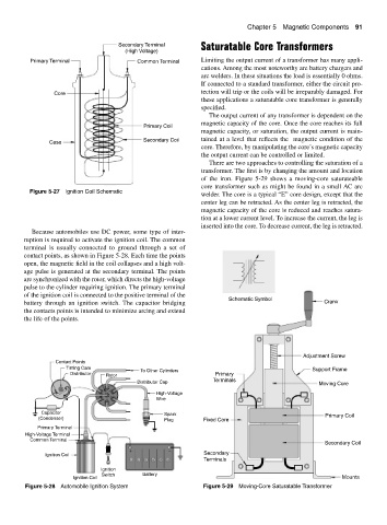
There are two approaches to controlling the saturation of a
transformer. The first is by changing the amount and location
of the iron. Figure 5-29 shows a moving-core saturateable
core transformer such as might be found in a small AC arc
Figure 5-27 Ignition Coil Schematic
welder. The core is a typical “E” core design, except that the
center leg can be retracted. As the center leg is retracted, the
magnetic capacity of the core is reduced and reaches satura-
tion at a lower current level. To increase the current, the leg is
inserted into the core. To decrease current, the leg is retracted.
Because automobiles use DC power, some type of inter-
ruption is required to activate the ignition coil. The common
terminal is usually connected to ground through a set of
contact points, as shown in Figure 5-28. Each time the points
open, the magnetic field in the coil collapses and a high volt-
age pulse is generated at the secondary terminal. The points
are synchronized with the rotor, which directs the high-voltage
pulse to the cylinder requiring ignition. The primary terminal
of the ignition coil is connected to the positive terminal of the
Schematic Symbol
battery through an ignition switch. The capacitor bridging Crank
the contacts points is intended to minimize arcing and extend
the life of the points.
Adjustment Screw
Contact Points
Timing Cam Support Frame
To Other Cylinders
Distributor Rotor Primary
Distributor Cap Terminals Moving Core
High-Voltage
Wire
Capacitor Spark
(Condenser) Primary Coil
Plug Fixed Core
Primary Terminal
High-Voltage Terminal
Common Terminal
Secondary Coil
+ −
Ignition Coil Secondary
Terminals
Ignition
Switch Battery
Ignition Coil Mounts
Figure 5-28 Automobile Ignition System Figure 5-29 Moving-Core Saturatable Transformer