
Page 139 - Electromechanical Devices and Components Illustrated Sourcebook
P. 139
Chapter 5 Magnetic Components 101
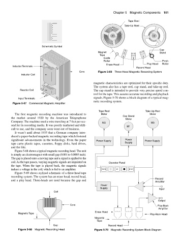
Tape Reel
Take-Up Reel
Schematic Symbol
Cap
Magnet Stand
Tape
Guide
Roller Pinch
Erase Head Play Head Roller
Inductor Terminals
Record Head
Core Figure 5-69 Three-Head Magnetic Recording System
Inductor Coil
magnetic characteristics are optimized for their specific duty.
The system also has a tape reel, cap stand, and take-up reel.
Reactor Coil The cap stand is intended to provide very precise speed con-
trol for the tape. This assures accurate recording and playback
signals. Figure 5-70 shows a block diagram of a typical mag-
Input Terminals
netic recording system.
Figure 5-67 Commercial Magnetic Amplifier
Tape Reel Take-Up Reel
The first magnetic recording machine was introduced to Motor Motor
Cap Stand
the market around 1920 by the American Telegraphone
Motor
Company. The machine used a wire traveling at 7 feet per sec-
M2 M3
ond for its recording media. It was poorly marketed and diffi-
M1
cult to use, and the company soon went out of business.
It wasn’t until about 1935 that a German company intro-
duced a paper-backed magnetic recording tape which fostered
significant advancements in the technology. From the paper Power Supply Power Power Supply
tape came plastic tapes, cassettes, floppy disks, hard drives, Supply
and the like.
Figure 5-68 shows a typical magnetic recording head. The unit
is simply an electromagnet with small gap (0.001 to 0.0005 inch).
The gap is placed onto a moving tape and a signal is applied to the
coil. As the tape passes, varying magnetic signals are imprinted on Operator Panel
the tape. When the tape is played back, the magnetic signals
induce a voltage in the coil, which is fed to an amplifier.
Figure 5-69 shows stylized schematic of a three-head tape
recording system. The system has an erase head, record head,
Record
and a play head. Three-heads are used because the gap and
Amplifier
Power
Supply Input
Coil
Output
Core Play-Back
Amplifier
Erase Head
Magnetic Tape Play-Back Head
Magnetic
Tape
Gap Record Head
Figure 5-68 Magnetic Recording Head Figure 5-70 Magnetic Recording System Block Diagram