
Page 188 - Electromechanical Devices and Components Illustrated Sourcebook
P. 188
150 Electromechanical Devices & Components Illustrated Sourcebook
When considering the type of electrical connectors to use in extremely common in home, commercial, and industrial
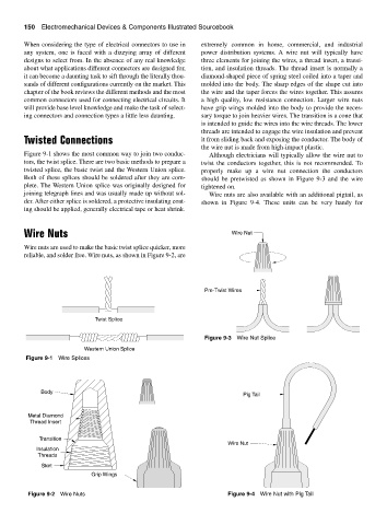
any system, one is faced with a dizzying array of different power distribution systems. A wire nut will typically have
designs to select from. In the absence of any real knowledge three elements for joining the wires, a thread insert, a transi-
about what applications different connectors are designed for, tion, and insulation threads. The thread insert is normally a
it can become a daunting task to sift through the literally thou- diamond-shaped piece of spring steel coiled into a taper and
sands of different configurations currently on the market. This molded into the body. The sharp edges of the shape cut into
chapter of the book reviews the different methods and the most the wire and the taper forces the wires together. This assures
common connectors used for connecting electrical circuits. It a high quality, low resistance connection. Larger wire nuts
will provide base level knowledge and make the task of select- have grip wings molded into the body to provide the neces-
ing connectors and connection types a little less daunting. sary torque to join heavier wires. The transition is a cone that
is intended to guide the wires into the wire threads. The lower
threads are intended to engage the wire insulation and prevent
Twisted Connections it from sliding back and exposing the conductor. The body of
the wire nut is made from high-impact plastic.
Figure 9-1 shows the most common way to join two conduc- Although electricians will typically allow the wire nut to
tors, the twist splice. There are two basic methods to prepare a twist the conductors together, this is not recommended. To
twisted splice, the basic twist and the Western Union splice. properly make up a wire nut connection the conductors
Both of these splices should be soldered after they are com- should be pretwisted as shown in Figure 9-3 and the wire
plete. The Western Union splice was originally designed for tightened on.
joining telegraph lines and was usually made up without sol- Wire nuts are also available with an additional pigtail, as
der. After either splice is soldered, a protective insulating coat- shown in Figure 9-4. These units can be very handy for
ing should be applied, generally electrical tape or heat shrink.
Wire Nuts Wire Nut
Wire nuts are used to make the basic twist splice quicker, more
reliable, and solder free. Wire nuts, as shown in Figure 9-2, are
Pre-Twist Wires
Twist Splice
Figure 9-3 Wire Nut Splice
Western Union Splice
Figure 9-1 Wire Splices
Body
Pig Tail
Metal Diamond
Thread Insert
Transition
Wire Nut
Insulation
Threads
Skirt
Grip Wings
Figure 9-2 Wire Nuts Figure 9-4 Wire Nut with Pig Tail