
Page 191 - Electromechanical Devices and Components Illustrated Sourcebook
P. 191
Chapter 9 Connectors 153
Wire
Wire Lug
Three-way Connector
Solder Joint
Wire Connector Locking
Oblong Turn Lock
Figure 9-15 Solder Lug
Flanged (M) Snap Plug
into the barrel and the joint is flooded with solder. After sol-
Serrated Ring (F) Snap Plug
dering it is important to remove all of the excess flux before
Hook (F) Small Quick insulating the joint.
Disconnect
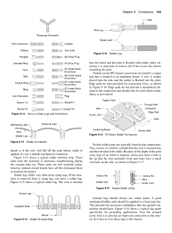
Printed circuit (PC) board connections are usually a copper
Side (M) Small Quick pad that is bonded to an insulating board. A wire is simply
Disconnect
placed into the hole and the solder is flooded into the joint.
(F) Large Quick
Double Ring Edge pads are also provided for connecting wires, as shown
Disconnect
in Figure 9-16. Edge pads do not provide a mechanical ele-
Ring (F) Large Quick
Disconnect ment to the connection and should only be used where redun-
dancy is not critical.
Low Clearance Flag
Copper Clad
Square Tip Small Pin
Through Pad
Round Tip Large Pin Wire Conductor
Edge Pad
Figure 9-12 Various Crimp Lugs and Connectors
Solder Joint
Wire
Mechanical Joint Soldered Joint
Insulating Board Solder Joint
Wire
Figure 9-16 PC Board Solder Connection
Solder Lug
Figure 9-13 Solder Connection
Socket solder joints are typically found in pin connections.
They consist of a hollow cylinder that the wire is inserted into
thumb is if the wire will fall off the joint before solder is
and then flooded with solder. Because of the depth of the joint
applied, it’s not a suitable mechanical connection.
some type of air relief is required. Some pins have a hole in
Figure 9-14 shows a typical solder terminal strip. These
the tip that the wire protrudes from and some have a small
units were the mainstay in electronic manufacturing during
vent hole on the side, as shown in Figure 9-17.
the vacuum tube era. These units are still available today;
however, printed circuit boards have all but eliminated them
in modern electronics.
Solder lugs differ very little from crimp lugs. If the insu- Hollow Pin Hollow Pin
lator is removed from a crimp lug, you have a solder lug. Wire
Figure 9-15 shows a typical solder lug. The wire is inserted Solder Vent Solder Joint
Figure 9-17 Socket Solder Joints
Solder Lugs
Ground lugs should always use solder joints. A good
mechanical/solder joint should be applied to a loop-type lug.
This provides the necessary redundancy that any ground con-
Insulation Strip
nection should have. Figure 9-18 shows a typical lug made
specifically for grounding applications. Note the serrated
Mount screw hole is to provide an improved connection to the chas-
Figure 9-14 Solder Terminal Strip sis. It is best to rivet these lugs to the chassis.