
Page 195 - Electromechanical Devices and Components Illustrated Sourcebook
P. 195
Chapter 9 Connectors 157
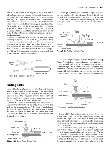
joint to be desoldered. After the joint is heated, the bulb is The flat spring binding post, as shown in Figure 9-28, is a
released and the solder is sucked off the joint. Solder suckers very old standard. The idea is to press down on the tab until
can be difficult to use and they don’t provide enough power the wire hook protrudes through the element. A wire is placed
for some joints. The preferred solder removal tool is the vacuum under the hook and the tab is released. The spring forces the
removal tool. These units operate in the same fashion as the wire against the hook and a solid electrical connection is
solder sucker, except that they have a spring loaded cylinder. made.
The piston is cocked into the down position. When the trigger
is pressed the piston is forced up and a high vacuum flow is
generated at the tip. These tools are very inexpensive and do Press
an excellent job of removing solder from electronic and elec- Wire Hook Down
trical solder joints. Flat Spring Brass Screw
Element Brass Nut
Delicate components can be severely damaged during
soldering operations due to overheating. To protect these Wire Lug
components, heat sinks are attached to the wire between the
To Circuit
component and the solder joint. As the joint is soldered, the Insulating
heat travels up the wire until it encounters the heat sink. It Board
then flows into the heat sink instead of the delicate compo- Brass Washers
nent. Figure 9-26 shows two examples of commercial heat Figure 9-28 Flat Spring Binding Post
sinks designed for soldering operations.
The coil spring binding post takes the flat spring unit a step
Heat Sinks
Alligator further. A plastic button is pressed down, which, inturn, com-
Type presses the coil spring below the through hole. A wire is
inserted through a slot in the button collar and through the wire
connection. When the button is released, the wire is forced into
Heat Sinks contact with the inside of the hole and a quality electrical con-
Flat Spring Type nection is made. Figure 9-29 shows a coil spring binding post.
Figure 9-26 Soldering Heat Sinks
Press
Down
Binding Posts Button
Wire Connection
The most fundamental connector is the binding post. Binding
posts have been around for as long as electricity has been utilized Brass Washers Coil Spring
by man. Binding posts may not represent the most elegant
method of connecting conductors; however, they do represent Insulating Board
the most reliable. Nothing produces a detachable electrical To Circuit
connection like an old fashioned nut and bolt.
Wire Lug
Figure 9-27 shows a basic binding post arrangement. A
Brass Screw
brass screw is attached to an insulating board and wire lug Brass Nut
with two flat washers and a nut. A thumb nut is installed onto Figure 9-29 Coil Spring Binding Post
the top of the screw. To attach a wire, simply wrap it around
the screw and tighten the thumb nut. For a more permanent
connection, the thumb nut can be replaced with a hex nut and Screw tight binding posts are intended to provide the con-
tightened with a nut driver. venience of a spring post and the connection quality of a nut
and bolt post. Figure 9-30 shows a typical screw tight binding
post. The thumb nut is screwed open, which lifts the clamping
Brass Screw
block and opens the wire connection. A wire is placed in and
the nut is tightened.
Thumb Nut The combination binding post, shown in Figure 9-31, car-
Wire Lug
ries the best features of all posts. It has a screw tight thumb
Brass Nut To Circuit nut with a wrap-around and through wire connection. The nut
Insulating Board is insulated and the top of the post carries a standard banana
jack. These units are generally supplied with a set of isolation
Brass Washers washers so that they can be mounted in a metal panel.
Figure 9-27 Brass Screw Binding Post Permanent connection can be made with a wire lug or to the