
Page 189 - Electromechanical Devices and Components Illustrated Sourcebook
P. 189
Chapter 9 Connectors 151
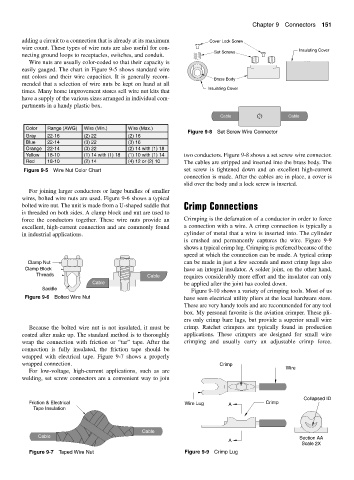
adding a circuit to a connection that is already at its maximum Cover Lock Screw
wire count. These types of wire nuts are also useful for con- Insulating Cover
Set Screws
necting ground loops to receptacles, switches, and conduit.
Wire nuts are usually color-coded so that their capacity is
easily gauged. The chart in Figure 9-5 shows standard wire
nut colors and their wire capacities. It is generally recom-
Brass Body
mended that a selection of wire nuts be kept on hand at all
Insulating Cover
times. Many home improvement stores sell wire nut kits that
have a supply of the various sizes arranged in individual com-
partments in a handy plastic box.
Cable Cable
Color Range (AWG) Wire (Min.) Wire (Max.)
Figure 9-8 Set Screw Wire Connector
Gray 22-16 (2) 22 (2) 16
Blue 22-14 (3) 22 (3) 16
Orange 22-14 (3) 22 (2) 14 with (1) 18
Yellow 18-10 (1) 14 with (1) 18 (1) 10 with (1) 14 two conductors. Figure 9-8 shows a set screw wire connector.
Red 18-10 (2) 14 (4) 12 or (2) 10 The cables are stripped and inserted into the brass body. The
Figure 9-5 Wire Nut Color Chart set screw is tightened down and an excellent high-current
connection is made. After the cables are in place, a cover is
slid over the body and a lock screw is inserted.
For joining larger conductors or large bundles of smaller
wires, bolted wire nuts are used. Figure 9-6 shows a typical
bolted wire nut. The unit is made from a U-shaped saddle that Crimp Connections
is threaded on both sides. A clamp block and nut are used to
force the conductors together. These wire nuts provide an Crimping is the defamation of a conductor in order to force
excellent, high-current connection and are commonly found a connection with a wire. A crimp connection is typically a
in industrial applications. cylinder of metal that a wire is inserted into. The cylinder
is crushed and permanently captures the wire. Figure 9-9
shows a typical crimp lug. Crimping is preferred because of the
speed at which the connection can be made. A typical crimp
Clamp Nut can be made in just a few seconds and most crimp lugs also
Clamp Block have an integral insulator. A solder joint, on the other hand,
Threads Cable requires considerably more effort and the insulator can only
Cable be applied after the joint has cooled down.
Saddle
Figure 9-10 shows a variety of crimping tools. Most of us
Figure 9-6 Bolted Wire Nut have seen electrical utility pliers at the local hardware store.
These are very handy tools and are recommended for any tool
box. My personal favorite is the aviation crimper. These pli-
ers only crimp bare lugs, but provide a superior small wire
Because the bolted wire nut is not insulated, it must be crimp. Ratchet crimpers are typically found in production
coated after make up. The standard method is to thoroughly applications. These crimpers are designed for small wire
wrap the connection with friction or “tar” tape. After the crimping and usually carry an adjustable crimp force.
connection is fully insulated, the friction tape should be
wrapped with electrical tape. Figure 9-7 shows a properly
wrapped connection. Crimp
For low-voltage, high-current applications, such as arc Wire
welding, set screw connectors are a convenient way to join
Collapsed ID
Friction & Electrical Wire Lug A Crimp
Tape Insulation
Cable
Cable Section AA
A
Scale 2X
Figure 9-7 Taped Wire Nut Figure 9-9 Crimp Lug