
Page 228 - Electromechanical Devices and Components Illustrated Sourcebook
P. 228
190 Electromechanical Devices & Components Illustrated Sourcebook
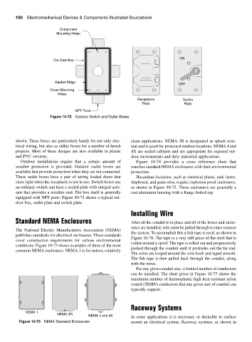
Component
Mounting Holes
ON
Die Cast Box
Gasket Ridge
OFF
Cover Mounting
Holes
Receptacle Switch
Plate Plate
NPT Ports
Figure 10-72 Outdoor Switch and Outlet Boxes
shown. These boxes are particularly handy for not only elec- clean applications. NEMA 3R is designated as splash resis-
trical wiring, but also as utility boxes for a number of bench tant and is good for protected outdoor locations. NEMA 4 and
projects. Most of these designs are also available in plastic 4X are sealed cabinets and are appropriate for exposed out-
and PVC versions. door environments and dirty industrial applications.
Outdoor installations require that a certain amount of Figure 10-74 provides a cross reference chart that
weather protection is provided. Outdoor outlet boxes are matches standard NEMA enclosures with their environmental
available that provide protection when they are not connected. protection.
These outlet boxes have a pair of spring loaded doors that Hazardous locations, such as chemical plants, tank farms,
close tight when the receptacle is not in use. Switch boxes use shipboard, and grain silos, require explosion proof enclosures,
an ordinary switch and have a sealed plate with integral actu- as shown in Figure 10-75. These enclosures are generally a
ator that provides a weather seal. The box itself is generally cast aluminum housing with a flange bolted top.
equipped with NPT ports. Figure 10-72 shows a typical out-
door box, outlet plate and switch plate.
Installing Wire
Standard NEMA Enclosures After all the conduit is in place and all of the boxes and enclo-
sures are installed, wire must be pulled through to inter-connect
The National Electric Manufacturers Association (NEMA)
the system. To accomplish this a fish tape is used, as shown in
publishes standards for electrical enclosures. These standards
Figure 10-76. The tape is a very stiff piece of flat steel that is
cover construction requirements for various environmental
coiled around a spool. The tape is rolled out and progressively
conditions. Figure 10-73 shows examples of three of the most
pushed through the conduit until it protrudes out the far end.
common NEMA enclosures. NEMA 1 is for indoor, relatively
The wires are looped around the wire hook and taped smooth.
The fish tape is then pulled back through the conduit, along
with the wires.
For any given conduit size, a limited number of conductors
can be installed. The chart given in Figure 10-77 shows the
maximum number of thermoplastic high heat resistant nylon
coated (THHN) conductors that any given size of conduit can
typically support.
Raceway Systems
NEMA 1
NEMA 3R
NEMA 4 and 4X
In some applications it is necessary or desirable to surface
Figure 10-73 NEMA Standard Enclosures mount an electrical system. Raceway systems, as shown in