
Page 234 - Electromechanical Devices and Components Illustrated Sourcebook
P. 234
196 Electromechanical Devices & Components Illustrated Sourcebook
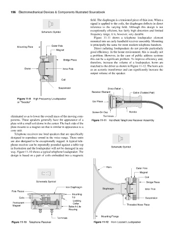
field. The diaphragm is a tensioned piece of thin iron. When a
signal is applied to the coils, the diaphragm deflects in direct
reference to the varying field. Although this design is not
exceptionally efficient, has fairly high distortion and limited
Schematic Symbol
frequency range, it is, however, very durable.
Figure 11-11 shows a telephone loudspeaker element
mounted into an early handheld receiver assembly. Mounting
is principally the same for most modern telephone handsets.
Outer Pole
Mounting Plate
Direct radiating loudspeakers do not provide particularly
Magnet
good efficiency. In the home environment, this is usually not
a problem. However, in the case of public address systems
this can be a significant problem. To improve efficiency and,
Bridge Piece
therefore, increase the volume of a loudspeaker, horns are
matched to the driver as shown in Figure 11-12. The horn acts
Dome Inner Pole as an acoustic transformer and can significantly increase the
output volume of the speaker.
Coil
Suspension Strain Relief
Receiver Element Cable (Twisted Pair)
Figure 11-9 High Frequency Loudspeaker
or “Tweeter” Ear Piece
Screw-On Cap Handle
eliminated so as to lower the overall mass of the moving com- Terminals
ponents. These speakers generally have the appearance of a Figure 11-11 Handheld Telephone Receiver Assembly
plate with a small soft dome in the center. The back side of the
plate mounts to a magnet set that is similar in appearance to a
cone unit.
Telephone receivers use loud speakers that are specifically
designed to reproduce sound in the voice range. These units
are also designed to be exceptionally rugged. A typical tele-
phone receiver can be repeatedly pounded against a table top
Schematic Symbol
in frustration and the loudspeaker will not be damaged in any
way. Figure 11-10 shows a typical telephone loudspeaker. The
design is based on a pair of coils embedded into a magnetic
Horn
Outer Pole
Magnet
Coil
Schematic Symbol Bridge Piece
Iron Diaphragm
Diaphragm Inner Pole
Pole Pieces
Mounting
Coils Lip Suspension
Locking
Permanent Collar
Magnet Threaded Nose Piece
Bake-A-Lite
Housing
Mounting Flange
Terminals
Figure 11-10 Telephone Receiver Figure 11-12 Horn Loaded Loudspeaker