
Page 238 - Electromechanical Devices and Components Illustrated Sourcebook
P. 238
200 Electromechanical Devices & Components Illustrated Sourcebook
in use today. A cup is packed with granulated carbon particles
and capped with a moving plate. The moving plate is con-
nected to a diaphragm mounted at the base of a mouthpiece. Coil
When a person speaks into the mouthpiece, the diaphragm Suspension Schematic
vibrates and transfers those vibrations to the moving plate. As Symbol
the plate moves, the carbon is packed tighter or allowed to
relax based on the diaphragm vibrations. As the granules move,
Outer Pole
the resistance of the carbon charge changes in direct reference
to the sound. Diaphragm
Permanent
By placing a loudspeaker (receiver) and a pair of batteries
Magnet
in a loop with the microphone, the current of the loop can be
Inner Pole
controlled by speaking into the microphone. Figure 11-26
shows a carbon microphone circuit. Coil Form
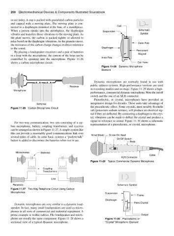
Figure 11-28 Dynamic Microphone
Element
Dynamic microphones are normally found in use with
public address systems. High-performance versions are used
Receiver
in recording studios and on stage. Figure 11-29 shows a high-
Microphone
performance, commercial dynamic microphone. Note the on/off
switch and the use of an XLR connector.
Piezoelectric, or crystal, microphones have provided an
inexpensive design for decades. These units take advantage of
Batteries
the piezoelectric effect. Some crystals, most notably Rochelle
Figure 11-26 Carbon Microphone Circuit
salt (potassium sodium tartrate), will produce an electrical sig-
nal if they are deflected. By connecting a diaphragm to the crys-
tal, vibrations can be made to deflect the crystal and produce a
signal in reference to sound. Figure 11-30 shows a schematic
For two-way communication, two sets consisting of a car-
representation of a piezoelectric, or crystal, microphone.
bon microphone, battery, coupling transformer, and receiver
can be arranged as shown in Figure 11-27. A simple system like
this can provide a reasonably good communications link over
Wind Shield Screw-On Head
several miles of cable. In some basic systems a “push-to-talk”
On/Off Switch
button is added to disconnect the batteries when not in use.
Body
ON OFF
Microphones Batteries
Cable
XLR Connector
Figure 11-29 Typical Commercial Dynamic Microphone
Coupling
Transformers
Line
Receivers Schematic Symbol
Figure 11-27 Two-Way Telephone Circuit Using Carbon
Microphones Suspension
Frame
Diaphragm
Piezo Crystal
Dynamic microphones are very similar to a dynamic loud-
speaker. In fact, many small loudspeakers are used as micro-
phones in all sorts of commercial and industrial equipment. A
prime example is walkie-talkies. The loudspeaker and micro- Output
phone are usually the same component. Figure 11-28 shows a Figure 11-30 Piezoelectric or
sectional view of a typical dynamic microphone. “Crystal” Microphone Element