
Page 242 - Electromechanical Devices and Components Illustrated Sourcebook
P. 242
204 Electromechanical Devices & Components Illustrated Sourcebook
Cross Bar
Cross Bars
Hydrophones Hydrophones
Rotating Mast
Hull Vertical Axis
Through Hull
Horizontal Axis
Headphones Hull Image
Bearing Indicator
Rotating Coaxial Mast
Hull
Sound
Hand Wheel Through Hull
Curves
Hull Image (Top View)
Horizontal Horizontal Bearing
Display
Indicator
Two-Channel Horizontal Hand Wheel
Amplifier
Hull Image (Side View)
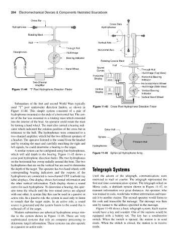
Figure 11-44 “T” Post Hydrophone Direction Finder Vertical Vertical Bearing
Display
Indicator
Vertical Hand Wheel
Submarines of the first and second World Wars typically
used “T” post underwater direction finders, as shown in Figure 11-45 Cross Post Hydrophone Direction Finder
Figure 11-44. This simple system consisted of a pair of
hydrophones mounted to the ends of a horizontal bar. The cen-
ter of the bar was mounted to a rotating mast which extended
into the interior of the boat. An operator could rotate the mast
by turning a hand wheel. The mast also carried a bearing indi-
cator which indicated the rotation position of the cross bar in Outer Hull
reference to the hull. The hydrophones were connected to a
two-channel amplifier, which fed the two different speakers of Sphere
a headset. The operator listened to the sound from the headset
Pressure Hull
and by rotating the mast and carefully matching the right and
Hydrophones
left signals, he could determine a bearing to the target.
A similar system can be configured using four hydrophones,
Figure 11-46 Spherical Hydrophone Array
which will add depth to the bearing. Figure 11-45 shows a
cross post hydrophone direction finder. The two hydrophones
on the horizontal bar sweep radially around the boat. The two
hydrophones that are on the vertical bar are used to determine
the depth of the target. The operator has two hand wheels with Telegraph Systems
corresponding bearing indicators and the outputs of the
hydrophones are connected to two-channel CRT (cathode ray Until the advent of the telegraph, communications were
tube) displays. One display shows horizontal information and restricted to mail or courier. The telegraph represented the
the other vertical information. Each display shows a sound first real time communication system. The telegraph relied on
curve for each hydrophone. To determine a bearing, the oper- Morse code, a dot/dash system shown in Figure 11-47, to
ator turns the wheels until the two sound curves are aligned transmit information over great distances. An operator, who
with one other. A system like this can be used in a passive or was trained in code, would take written information and trans-
active role. In a passive role the system is used only to listen mit it to another station. The second operator would listen to
to sounds that the target emits. In an active role, a sound the code and transcribe the message. The message was then
source is generated and the system listens to the sound that is sent by runner to the address specified in the message.
reflected off of the target. Figure 11-48 shows a basic telegraph system. Each station
Modern submarines use spherical hydrophone arrays sim- would have a key and sounder. One of the stations would be
ilar to the system shown in Figure 11-46. These are very equipped with a battery set. The key has a send/receive
sophisticated systems that rely on computer processing to switch. When the switch is opened, the station is in send
determine target information. These systems can also operate mode. When the switch is closed, the station is in receive
in a passive or active role. mode.