
Page 244 - Electromechanical Devices and Components Illustrated Sourcebook
P. 244
206 Electromechanical Devices & Components Illustrated Sourcebook
Lower Stop Adjustment
Iron Bar Upper Stop Adjustment
Pivot
Tension Adjustment
Pivot Bar
Anvil
Return Spring
Terminal
Base
Rubber Foot
Coil
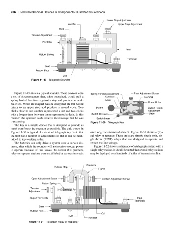
Figure 11-49 Telegraph Sounder
Figure 11-49 shows a typical sounder. These devices were Spring Tension Adjustment Pivot Adjustment Screw
a set of electromagnets that, when energized, would pull a Contacts Terminal
spring loaded bar down against a stop and produce an audi- Lever
Mount Holes
ble click. When the magnet was de-energized the bar would
return to an upper stop and produce a second click. Two Button Button Height
clicks close to one another represented a dot and two clicks Adjustment
with a longer time between them represented a dash. In this Switch Contacts Base
manner, the operator could receive the message that he was Switch Lever
transposing. Figure 11-50 Telegraph Key
The key is a simple device that is designed to provide as
much comfort to the operator as possible. The unit shown in
Figure 11-50 is typical of a standard telegraph key. Note that over long transmission distances. Figure 11-51 shows a typi-
the unit has a number of adjustments so that it can be main- cal relay or repeater. These units are simply single-pole, sin-
tained in top working order. gle throw (SPST) relays that are designed to operate and
The batteries can only drive a system over a certain dis- switch the line voltage.
tance, after which the sounder will not receive enough power Figure 11-52 shows a schematic of a telegraph system with a
to operate because of line losses. To correct this problem, single relay station. It should be noted that several relay stations
relay or repeater stations were established at various intervals may be deployed over hundreds of miles of transmission line.
Contacts
Rubber Stop
Frame
Open Adjustment Screw Contact Adjustment Screw
Return Spring
Tension
Adjustment
Output Terminals Input
Terminals
Base
Rubber Foot
Coil
Pivot
Iron Bar
Figure 11-51 Telegraph Relay or Repeater