Page 246 - Electromechanical Devices and Components Illustrated Sourcebook
P. 246

208 Electromechanical Devices & Components Illustrated Sourcebook

                                                                                     Rear Panel
                                                                             Wooden Cabinet
                                                                           Front Panel


                                                              Magneto
                                                                             Ringer
                                                               Crank

                        Earpiece
                                                                 Mouthpiece

                                                                     Shelf


                                                                         Battery Compartment
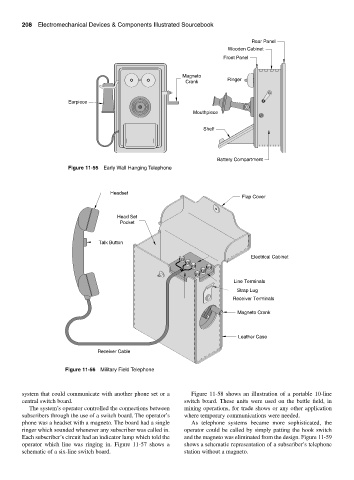
                        Figure 11-55 Early Wall Hanging Telephone


                                      Headset
                                                                                  Flap Cover


                                        Head Set
                                         Pocket


                                  Talk Button

                                                                                     Electrical Cabinet


                                                                               Line Terminals
                                                                                Strap Lug
                                                                               Receiver Terminals

                                                                                Magneto Crank


                                                                                Leather Case

                                  Receiver Cable

                       Figure 11-56 Military Field Telephone


        system that could communicate with another phone set or a  Figure 11-58 shows an illustration of a portable 10-line
        central switch board.                                 switch board. These units were used on the battle field, in
           The system’s operator controlled the connections between  mining operations, for trade shows or any other application
        subscribers through the use of a switch board. The operator’s  where temporary communications were needed.
        phone was a headset with a magneto. The board had a single  As telephone systems became more sophisticated, the
        ringer which sounded whenever any subscriber was called in.  operator could be called by simply patting the hook switch
        Each subscriber’s circuit had an indicator lamp which told the  and the magneto was eliminated from the design. Figure 11-59
        operator which line was ringing in. Figure 11-57 shows a  shows a schematic representation of a subscriber’s telephone
        schematic of a six-line switch board.                 station without a magneto.
   241   242   243   244   245   246   247   248   249   250   251