
Page 251 - Electromechanical Devices and Components Illustrated Sourcebook
P. 251
Chapter 12 Lighting 213
Base Glass Tube Glass Tube
Filament
Bimetal Strip
Neon Gas
Fixed Contact
Mercury Vapor
Terminals
White Luminescent Coating Moving Contact
Figure 12-4 Fluorescent Light Bulb
Terminal Wires
These lamps consist of a long tube with a filament at both
ends. The tube is filled with an argon/mercury atmosphere.
The inside surface of the tube is coated with a white fluores- Figure 12-6 Glow Switch Starter
cent material. To start the tube, power is fed to the filaments,
which produce intense electron emission and heat. After the
tube is heated up, a voltage is applied across the two different
filaments and over the length of the tube. The gas within the
tube becomes excited and produces ultraviolet light. The Starter
ultraviolet light excites the fluorescent coating which, in turn,
produces visible light.
Figure 12-5 shows a simple starting circuit for a fluores-
cent tube. Pressing the start switch makes the filaments glow.
After the tube heats up, the switch is released and power is
Filaments Fluorescent Tube
redirected between the filaments and over the length of the
tube, which, in turn, forces the gas charge to glow. To turn the
lamp off, the power is disconnected.
Power
Ballast
Start Switch
Figure 12-7 Fluorescent Light Bulb Starting Circuit with
Ballast
Filaments Fluorescent Tube
Since a fluorescent tube has very little resistance when
Power operating, it is necessary to use a ballast in the power circuit,
Figure 12-5 Fluorescent Light Bulb Starting as shown in Figure 12-7. The principal function of the ballast
Circuit is to provide a high-voltage spike when the starter contacts
open, and to limit the current once the lamp is operating.
Figure 12-8 shows a typical commercial lamp ballast.
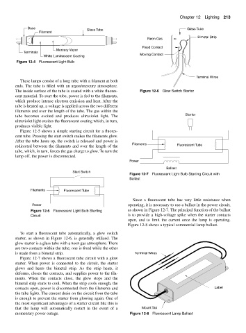
To start a fluorescent tube automatically, a glow switch
starter, as shown in Figure 12-6, is generally utilized. The
glow starter is a glass tube with a neon gas atmosphere. There
are two contacts within the tube; one is fixed while the other
is made from a bimetal strip. Terminal Wires
Figure 12-7 shows a fluorescent tube circuit with a glow
starter. When power is connected to the circuit, the starter
glows and heats the bimetal strip. As the strip heats, it
deforms, closes the contacts, and supplies power to the fila-
ments. When the contacts close, the glow stops and the
bimetal strip starts to cool. When the strip cools enough, the
contacts open, power is disconnected from the filaments and Label
the tube lights. The current drain on the circuit from the tube
is enough to prevent the starter from glowing again. One of
the most significant advantages of a starter circuit like this is
that the lamp will automatically restart in the event of a Mount Tab
momentary power outage. Figure 12-8 Fluorescent Lamp Ballast