
Page 253 - Electromechanical Devices and Components Illustrated Sourcebook
P. 253
Chapter 12 Lighting 215
This, in turn, ionizes the gas and it starts to glow. When the 5500 F (3040 C), it slowly evaporates and releases tungsten
gas becomes ionized, its resistance lowers and the voltage of atoms. The tungsten atoms migrate towards the bulb, which is
the transformer is pulled down to the operation voltage, usu- at approximately 1340 F (730 C). Near or at the bulb, the
ally around 400 volts. tungsten atoms combine with the oxygen and halogen atoms,
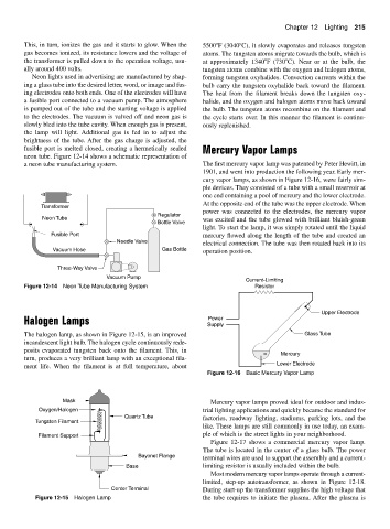
Neon lights used in advertising are manufactured by shap- forming tungsten oxyhalides. Convection currents within the
ing a glass tube into the desired letter, word, or image and fus- bulb carry the tungsten oxyhalide back toward the filament.
ing electrodes onto both ends. One of the electrodes will have The heat from the filament breaks down the tungsten oxy-
a fusible port connected to a vacuum pump. The atmosphere halide, and the oxygen and halogen atoms move back toward
is pumped out of the tube and the starting voltage is applied the bulb. The tungsten atoms recombine on the filament and
to the electrodes. The vacuum is valved off and neon gas is the cycle starts over. In this manner the filament is continu-
slowly bled into the tube cavity. When enough gas is present, ously replenished.
the lamp will light. Additional gas is fed in to adjust the
brightness of the tube. After the gas charge is adjusted, the
fusible port is melted closed, creating a hermetically sealed Mercury Vapor Lamps
neon tube. Figure 12-14 shows a schematic representation of
a neon tube manufacturing system. The first mercury vapor lamp was patented by Peter Hewitt, in
1901, and went into production the following year. Early mer-
cury vapor lamps, as shown in Figure 12-16, were fairly sim-
ple devices. They consisted of a tube with a small reservoir at
one end containing a pool of mercury and the lower electrode.
At the opposite end of the tube was the upper electrode. When
Transformer
power was connected to the electrodes, the mercury vapor
R Regulator
Neon Tube was excited and the tube glowed with brilliant bluish-green
Bottle Valve
light. To start the lamp, it was simply rotated until the liquid
Fusible Port mercury flowed along the length of the tube and created an
Needle Valve
electrical connection. The tube was then rotated back into its
Vacuum Hose Gas Bottle operation position.
Three-Way Valve
Vacuum Pump
Current-Limiting
Figure 12-14 Neon Tube Manufacturing System Resistor
Upper Electrode
Halogen Lamps Supply
Power
The halogen lamp, as shown in Figure 12-15, is an improved Glass Tube
incandescent light bulb. The halogen cycle continuously rede-
posits evaporated tungsten back onto the filament. This, in
Mercury
turn, produces a very brilliant lamp with an exceptional fila-
Lower Electrode
ment life. When the filament is at full temperature, about
Figure 12-16 Basic Mercury Vapor Lamp
Mask Mercury vapor lamps proved ideal for outdoor and indus-
Oxygen/Halogen trial lighting applications and quickly became the standard for
Quartz Tube factories, roadway lighting, stadiums, parking lots, and the
Tungsten Filament
like. These lamps are still commonly in use today, an exam-
Filament Support ple of which is the street lights in your neighborhood.
Figure 12-17 shows a commercial mercury vapor lamp.
The tube is located in the center of a glass bulb. The power
Bayonet Flange terminal wires are used to support the assembly and a current-
Base limiting resistor is usually included within the bulb.
Most modern mercury vapor lamps operate through a current-
limited, step-up autotransformer, as shown in Figure 12-18.
Center Terminal During start-up the transformer supplies the high voltage that
Figure 12-15 Halogen Lamp the tube requires to initiate the plasma. After the plasma is