
Page 258 - Electromechanical Devices and Components Illustrated Sourcebook
P. 258
220 Electromechanical Devices & Components Illustrated Sourcebook
more commonly found as an assembly, as shown in Figure 12-35. Xenon Lamps
In this case, the reflector is designed to mount a high intensity
halogen lamp at the focal point of the reflector. The assembly Most of us have experienced a xenon flash unit in our cam-
has a stray light shield mounted to the center of the flat lens. The eras. A xenon flash tube is an integral part of almost every
lens is intended to keep dust and dirt off of the reflector. camera manufactured today.
Bezel
Trigger Plate
Flat Lens Xenon Gas
Parabolic Reflector
Terminals
Electrodes
Mirrored Surface Quartz Tube
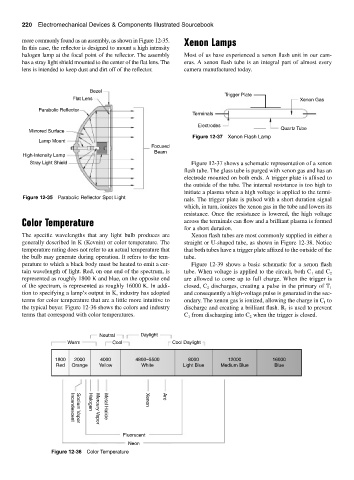
Figure 12-37 Xenon Flash Lamp
Lamp Mount
Focused
Beam
High-Intensity Lamp
Stray Light Shield Figure 12-37 shows a schematic representation of a xenon
flash tube. The glass tube is purged with xenon gas and has an
electrode mounted on both ends. A trigger plate is affixed to
the outside of the tube. The internal resistance is too high to
initiate a plasma when a high voltage is applied to the termi-
Figure 12-35 Parabolic Reflector Spot Light nals. The trigger plate is pulsed with a short duration signal
which, in turn, ionizes the xenon gas in the tube and lowers its
resistance. Once the resistance is lowered, the high voltage
Color Temperature across the terminals can flow and a brilliant plasma is formed
for a short duration.
The specific wavelengths that any light bulb produces are Xenon flash tubes are most commonly supplied in either a
generally described in K (Kevnin) or color temperature. The straight or U-shaped tube, as shown in Figure 12-38. Notice
temperature rating does not refer to an actual temperature that that both tubes have a trigger plate affixed to the outside of the
the bulb may generate during operation. It refers to the tem- tube.
perature to which a black body must be heated to emit a cer- Figure 12-39 shows a basic schematic for a xenon flash
tain wavelength of light. Red, on one end of the spectrum, is tube. When voltage is applied to the circuit, both C and C 2
1
represented as roughly 1800 K and blue, on the opposite end are allowed to come up to full charge. When the trigger is
of the spectrum, is represented as roughly 16000 K. In addi- closed, C discharges, creating a pulse in the primary of T 1
2
tion to specifying a lamp’s output in K, industry has adopted and consequently a high-voltage pulse is generated in the sec-
terms for color temperature that are a little more intuitive to ondary. The xenon gas is ionized, allowing the charge in C to
1
the typical buyer. Figure 12-36 shows the colors and industry discharge and creating a brilliant flash. R is used to prevent
1
terms that correspond with color temperatures. C from discharging into C when the trigger is closed.
2
1
Neutral Daylight
Warm Cool Cool Daylight
1800 2000 4000 4800–5500 8000 12000 16000
Red Orange Yellow White Arc Light Blue Medium Blue Blue
Xenon
Halogen
Metal Halide
Incandescent
Sodium Vapor
Mercury Vapor
Fluorscent
Neon
Figure 12-36 Color Temperature