Page 263 - Electromechanical Devices and Components Illustrated Sourcebook
P. 263

Chapter 13  Meters 225

                                                                                                 Zero Adjustment
                                                                     Terminal
         Permanent                                 Scale                                        Tension Adjustment
           Magnet
                                                                                                   Zero Lock
                                                               Upper Plate
                               .5  1   1.5
                                           2
                                  VOLTS
                                                               Uprights
                                                                                                     Suspension
                                                    Coil                                               Wire
              Needle
                                                   Bridge         Poles
                                   N
                                                                                                      Needle
                         N                  S
                                                                                 4  3  2  1  0  1  2 3 4  Scale
                                   S                                                  VOLTS
                     Pivot                                                     N             S
                                                Pole Faces
                 Moving Vane                                                                          Iron Core
                                           Spring              Moving Coil
         Figure 13-5 Permanent Magnet Galvanometer               Preload                             Permanent
                                                                 Spring                               Magnet
                                                                                                         Leveling
                                                                Terminal                                  Foot
        a baseboard and a toy compass is placed on top of a thread
        spool in the middle of the coil.
                                                                                                          Base
           The permanent magnet galvanometer is designed to oper-
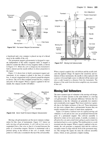
        ate independent of the earth’s magnetic field. A magnet is  Figure 13-7 Moving Coil Galvanometer
        added to counter the effects of stray magnetic fields, as shown
        in Figure 13-5. When the coil is energized, the instrument’s
        field is altered and the needle deflects in direct proportion to
        the signal.
                                                              When a signal is applied, the coil deflects and the needle indi-
           Figure 13-6 shows how to build a permanent magnet gal-
                                                              cates the applied voltage. To improve the sensitivity and res-
        vanometer. A toy compass is glued to the base of a plastic
                                                              olution of these instruments, the needle is often replaced with
        box. A curved, magnetized strip is placed around the magnet,
                                                              a mirror. A focused light source is reflected off the mirror and
        as shown. The coil is then wrapped around the box, compass,
                                                              onto a scale located at a distance from the instrument. The
        and poles of the magnet. When a signal is applied to the ter-
                                                              distance of the scale from the mirror amplifies any movement
        minals, the compass needle will deflect.
                                                              of the coil.
                                                              Moving Coil Voltmeters
                                                Magnetized
                 Terminal                          Strip
                                                              The most common type of voltmeter is the moving coil design.
                                                              This type of meter operates in the same fashion as a moving
           Toy                                       Plastic  coil galvanometer. The principal difference between the two
         Compass                                      Box
                                                              instruments is that the voltmeters are generally less sensitive
                                                              and considerably more rugged. Their lower sensitivity is gener-
                                                    Coil
                                                              ally due to the higher resistance of the coil. These instruments
                                                              are also more compact than a galvanometer because they are
                                         Terminal
                                                              usually mounted into a panel or stand-alone equipment.
                                                                 Figure 13-8 shows a stylized view of a typical moving coil
         Figure 13-6 Bench Built Permanent Magnet Galvanometer
                                                              voltmeter. A coil and an iron core are positioned between the
                                                              poles of a permanent magnet.  The coil/core assembly is
                                                              allowed to rotate on two pivot points. A needle, or pointer, is
           Moving coil galvanometers are the most common configu-  affixed to the core and a small clock spring is used to return the
        ration for this class of instruments. Figure 13-7 shows an  mechanism back to a zero reading. The needle points to a scale
        early moving coil galvanometer. A coil, with an iron core, is  mounted onto the magnet. When a signal is applied to the ter-
        suspended from a fine wire so that it is located between the  minals, the coil generates a magnetic field and the coil/core
        poles of a horseshoe magnet. Tension is maintained with a  assembly rotates to align with the field of the permanent mag-
        preload spring at the bottom of the coil.  A needle, which  net. The stronger the signal, the more the coil/core assembly
        points to a volts scale, is mounted to the top of the coil assembly.  rotates, which, in turn, generates a higher reading.
   258   259   260   261   262   263   264   265   266   267   268