Page 265 - Electromechanical Devices and Components Illustrated Sourcebook
P. 265

Chapter 13  Meters 227

           Another method to read higher voltages with a low volt-                            Multiply Reading by 10
        meter is to incorporate a voltage divider, as discussed in
        Chapter 4. Figure 13-12 shows a 10-volt meter configured to
                                                                     1 volt,
        accept a 0- to 100-volt input signal. This method is normally  (100 megohm)
        not used on analog meters because the current loss over the
        circuit can be fairly high. This, in turn, affects the sensitivity
        of the meter. As an example, the circuit shown would require
                                                               Range Selector
        a 10-mA drive current to read full scale.
                                                                          1 volts       1000 volts

              Multiply                                                       10 volts  100 volts
           Reading by 10
                                        10 volt, 100 _a Meter     +                                         −
                                           (100 ohm)                   90 megohm 9 megohm  900 K  100 K
                      1 2 3  4  5 6 7 8 9                                    100-Megohm Input Impedance
                                10
                       DC VOLTS          Mirror                Figure 13-14 Digital Voltmeter with Four Range Voltage Divider
                                         Needle
                                         Stops
                                                                 If an extremely high input impedance is required while
                                         Zero Adjust
                                                              using a moving coil voltmeter, then an amplifier must be
                     −         +                              incorporated, as shown in Figure 13-15. The voltage divider
                                                              network is the same as with a digital voltmeter. The output of
                                                              the selector switch is fed through a calibration potentiometer
                                                              and then into an amplifier, which, in turn, drives the meter.
                −                              +              The calibration adjustment is intended to tune the input signal
                       1 k ohms    9 k ohms
                                                              to the amplifier so that the meter can be referenced against a
                         0- to 100-volt Output                standard voltage.
           Figure 13-12 Voltmeter with Voltage Divider Compen-
           sation Resistors


                                                                                   3 4 5  6  7
                                                                                1 2      8 9
                                                                                           10
                          Multiply Reading by 10                                  DC VOLTS
                                                                                                      0 to 10 volts
                                     10 volt, (100 megohms)

                                                                                +         −
             −                              +
                   2 megohms  18 megohms
                      0- to 100-volt Input
                                                                  Amplifier
             Figure 13-13 Digital Voltmeter with Voltage Divider
             Resistors

                                                                Calibration
                                                               Potentiometer
           Voltage dividers are more commonly used on digital
        meters, as shown in Figure 13-13. Because a digital meter has  Range
        an extremely high input impedance, the resistors that are used  Selector
        for the voltage divider can be in the megohm range and, there-  1 volts      1000 volts
        fore, require very low driving currents. As an example, the
        circuit shown would only require a 0.5- A drive current to       10 volts  100 volts
        read full scale.                                                                                 −
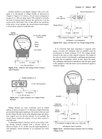
           A multirange digital voltmeter can be set up using a volt-  +
                                                                   90 megohm 9 megohm 900 k ohm 100 k ohm
        age divider network coupled with a selector switch, as
        shown in Figure 13-14. In this case the input impedance is       100-megohm Input Impedance
        100 megohms, which translates to an extremely low drive  Figure 13-15 Amplified Analog Voltmeter with Four Range
        current.                                               Voltage Divider
   260   261   262   263   264   265   266   267   268   269   270