
Page 267 - Electromechanical Devices and Components Illustrated Sourcebook
P. 267
Chapter 13 Meters 229
scaling the current reading. When measuring ohms in this
fashion the ohms scale is logarithmic so a conversion from the 1 2 3 4 5 6 7 8 9 Scale
current reading can be calculated with Ohm’s law. Use the VOLTS 10
following formula to convert the current reading of this circuit
Needle
to ohms:
Fixed Iron Core
[1.5 (battery volts) (indicated current)] range ohms
Bridge Moving Iron Core
Doing the math every time you measure a resistor is a lit-
Pivot Coil
tle inconvenient, so a special meter face can be printed and
glued over the existing face. The special face should have
Return Spring
both current and Ohms scales as shown in the illustration. Terminals
This will make the meter movement direct reading in the X1
range. The ohms indication is simply multiplied by the range Figure 13-20 Repulsion Vane Voltmeter
for higher resistance values.
Plunger Type Voltmeters
Dynamometer Voltmeters
Figure 13-19 shows a plunger type voltmeter mechanism. The
movement is a needle that is affixed to an iron core piece. The This type of voltmeter does not rely on permanent magnets or
bottom of the core carries an axle, which is mounted into a iron cores. In this arrangement, the signal itself generates the
pivot set. A clock spring is utilized to return the movement opposing magnetic fields to provide the requisite deflection.
back to zero. The iron core piece has a circular vane protrud- Three coils are used in the design, two are fixed and the third
ing from the right side. Just below the far end of the vane, a is a moving coil mounted in a pivot set with a clock spring.
solenoid coil is positioned so that its magnetic field will act on The two fixed coils are aligned so as to provide a uniform
the iron vane. When a signal is applied to the coil, the plunger magnetic field. The moving coil is placed off-axis and in
is pulled into the coil in direct proportion to the strength of the opposition to the fixed coils. When a signal is applied to the
magnetic field produced. coils, the moving coil deflects in direct proportion to strength
of the applied voltage. Figure 13-21 shows a dynamometer
voltmeter arrangement.
Scale
1 2 3 4 5 6 7 8 9 10
VOLTS
Needle
Moving Coil
Iron Vane
Bridge Fixed Coil
Terminals
Fixed Coil
Pivot
Solenoid Coil
Return Spring Schematic
Figure 13-19 Plunger Type Voltmeter Scale
1 2 3 4 5 6 7 8 9
DC VOLTS 10
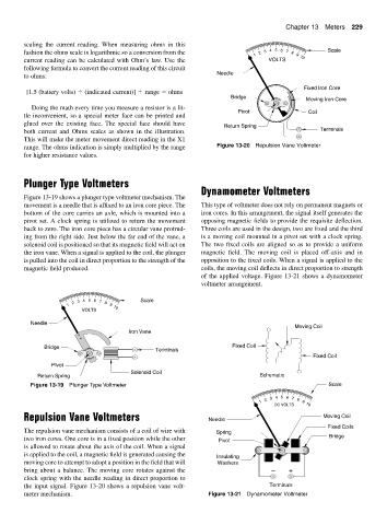
Repulsion Vane Voltmeters Needle Moving Coil
Fixed Coils
The repulsion vane mechanism consists of a coil of wire with Spring
two iron cores. One core is in a fixed position while the other Pivot Bridge
is allowed to rotate about the axis of the coil. When a signal
is applied to the coil, a magnetic field is generated causing the Insulating
moving core to attempt to adopt a position in the field that will Washers
bring about a balance. The moving core rotates against the − +
clock spring with the needle reading in direct proportion to
the input signal. Figure 13-20 shows a repulsion vane volt- Terminals
meter mechanism. Figure 13-21 Dynamometer Voltmeter